Amplifier Circuit
WIRELESS_VIDEO_CAMERA_LINK
Published:2009/7/9 2:21:00 Author:May | From:SeekIC

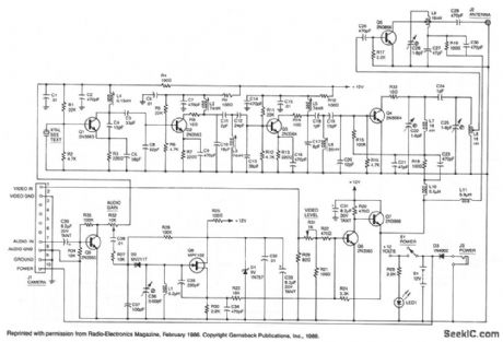
This high-performance video-camera link transmits signals from your video camera to your VCR, or from your VCR to TVs throughout your home. The first stage of the rf chain is a crystal-controlled oscillator, Q1, with a frequency of 60 to 65 MHz, which is one-eighth of the final output frequency. The oscillator produces a signal of about +6 dBm (4 mW) that drives three stages of frequency doublers. The combined action of those doublers multiplies the input frequency by eight for a final output frequency of (nominally) 500 MHz. Double-tuned circuits are used between each stage to help reduce spurious outputs that might cause unwanted interference. The video input signal from your VCR, video camera, etc. drives a video modulator, Q6 and Q7, that adds the video signal to the + 12 V line supplying power to the final doubler, Q4, and the output amplifier, Q5. That method of modulation is similar to the way a conventional AM-radio transmitter is modulated. The video modulator has a nominal bandwidth of five MHz. The audio input is applied to Q8, which operates as a VCO running at a nominal frequency of 4.5 MHz to produce the modulated sound carrier. For simplicity, Q8 is a free-running oscillator, since the ±25 kHz frequency deviation that is required would be very difficult to produce at that frequency with a crystal-controlled oscillator. Besides, most TV sound systems will accept a ± 10 kHz error in the sound-carrier frequency without producing undue distortion, and that greatly simplifies the circuitry required. The kit is available from North Country Radio, P.O. Box 53, Wykagyl Station, NY 10804.
Reprinted Url Of This Article:
http://www.seekic.com/circuit_diagram/Amplifier_Circuit/WIRELESS_VIDEO_CAMERA_LINK.html
Print this Page | Comments | Reading(3)

Article Categories
power supply circuit
Amplifier Circuit
Basic Circuit
LED and Light Circuit
Sensor Circuit
Signal Processing
Electrical Equipment Circuit
Control Circuit
Remote Control Circuit
A/D-D/A Converter Circuit
Audio Circuit
Measuring and Test Circuit
Communication Circuit
Computer-Related Circuit
555 Circuit
Automotive Circuit
Repairing Circuit
Code: