
Circuit Diagram
Index 753
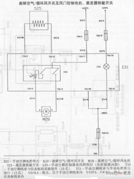
Zhonghua Car Air Conditioning System Circuit (the 3rd)
Published:2011/7/18 5:04:00 Author:Felicity | Keyword: Zhonghua Car, Air Conditioning System, Circuit
View full Circuit Diagram | Comments | Reading(896)
Zhonghua Car Air Conditioning System Circuit (the 4th)
Published:2011/7/18 5:05:00 Author:Felicity | Keyword: Zhonghua Car, Air Conditioning System, Circuit
View full Circuit Diagram | Comments | Reading(504)
PULSE_COINCIDENCE_DETECTOR
Published:2009/7/16 23:20:00 Author:Jessie

Provides output from silicon controlled switches only when input pulses are applied simultaneously at A und B, with 2 to 3 v amplitude. Over-lap of 1 microsec is sufficient for triggering.- Transistor Manual, Seventh Edition, General Electric Co., 1964, p 428. (View)
View full Circuit Diagram | Comments | Reading(2709)
PLATL_TO_GRID_COUPLED_MAIN_GATE_MVBR
Published:2009/7/16 23:20:00 Author:Jessie

Triggered by connecting plate of trigger inverter or switch tube in parallel with plate of normally-off mvbr tube. Unblanking gate is generated at mvbr as negative output. Used in radar to provide pate during which display sweep is generated, together with gates for generating waveforms that must be coincident with display sweep.-NBS, Handbook Preferred Circuits Navy Aeronautical Electronic Equipment, Vol. 1, Electron Tube Circuits, 1963, p N10-2. (View)
View full Circuit Diagram | Comments | Reading(667)
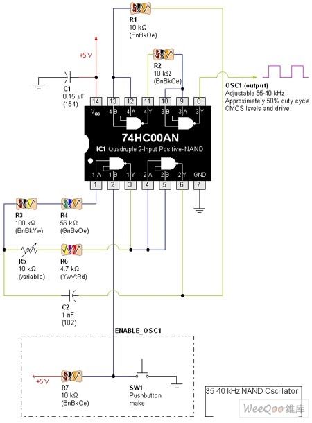
35KHz-40KHz Standard Square-wave Generator Circuit
Published:2011/7/18 5:14:00 Author:Felicity | Keyword: 35KHz-40KHz, Standard Square-wave Generator, Circuit
View full Circuit Diagram | Comments | Reading(1917)
BISTABLE_INDICATOR_LAMP_DRIVER
Published:2009/7/16 23:18:00 Author:Jessie

Permits controlling lamp with short trigger pulses, for control panel of computer. Negative 2-V trigger at A turns on lamp, which then remains on due to regenerative feedback in circuit. Positive pulse at A turns out lamp. Use of complementary-type transistors minimizes standby power when lamp is out.- Transistor Manual, Seventh Edition, General Electric Co., 1964, p 202. (View)
View full Circuit Diagram | Comments | Reading(833)
ACTIVE_LOAD
Published:2009/7/12 22:24:00 Author:May

National NSL4944 constantcurrent LED serves as cuffent source for collector resistor of Schmitt trigger to provide up to 12-V output at 40 mA for lamp load. When lamp andQ2 are off, most of LED current flows through 100-ohm resistor to determine circuit trip point of 2 V. When control signal saturates Q1, Q2 provides about 1 V for lamp to give some preheating and reduce starting cument surge.When control is above trip point, Q2 tums on and energizes lamp.-''Linear Applications, Vol.2,''National Semiconductor,Santa Clara, CA,1976,AN-153,P 3.
(View)
View full Circuit Diagram | Comments | Reading(972)
FILAMENT_EMISSION_REGULATOR
Published:2009/7/12 22:24:00 Author:May

Used in Consolidated Electrodynamics gas analyzer to control ionizing current strength by regulating filament temperature of cycloid tube Potentiometer used for control is in grid circuit of V251. Circuit maintains ionizing current automaticcdly at desired level-G.C.Carroll, Industrial Instrumenl Servicing Handbook, McGraw-Hill,N,Y,1960,p8-122 (View)
View full Circuit Diagram | Comments | Reading(683)
RAIL_SPLITTER_VIRTUAL_GROUND_CIRCUIT
Published:2009/7/16 23:18:00 Author:Jessie

Use a low-power op amp, of which there are many to choose from. The National LF441 is a good, inexpensive choice (don't confuse it with the 411). Pin 6 is the virtual ground output. This circuit will work correctly down to a battery voltage of about 6V. The current consumption is about 160 μA. (View)
View full Circuit Diagram | Comments | Reading(2016)
12_V_AT_10_A_FOR_HOUSE
Published:2009/7/16 23:17:00 Author:Jessie

Power supply is more than adequate for handling 12-V FM transceiver and even small amplifier. Series combination of three 6.3-V 10-A filament transformers drives 12-A 50-PIV bridge rectifier supplying 18 VDC to National LM305 regulator and pass transistors. Output voltage is at least 4 V less. Circuit provides foldback-current limiting for protection against load shorts. 500-ohm pot varies output from 11.2 to 14.1 V. Q1 is 2N2905, Q2 is 2N3445, and Q3 is 2N3772. T1-T3 are 6.3 V at 10 A (Essex Stancor P-6464 or equivalent ).-C. Car-roll, That's a Big 12 Volts, QST, Aug. 1976, p 26-27. (View)
View full Circuit Diagram | Comments | Reading(3820)
ACQUISITION_RELAY_DRIVER
Published:2009/7/12 22:22:00 Author:May

Scr Q3 and transistor Q4 provide stable triggering point for acquisition signal used in aligning missile guidance systems, without hysteresis effect.-W.S. Zukowsky, Aligning Saturn Missile's Guidance System, Electronics, 37:8, p26-27. (View)
View full Circuit Diagram | Comments | Reading(678)
SPEEDING_ONE_SHOT_RECOVERY
Published:2009/7/16 23:16:00 Author:Jessie

Additional transistor Q3 reduces charging time of timing capacitor, thereby increasing duty cycle. With values shown, circuit provides 10-microsec pulses with recovery time of 0.25 microsec, corresponding to repetition rate of almost 100,000 pps and 97.5% duty cycle.-W.A. Ross, Added Transistor Reduces One-Shot Recovery Time, EEE, 12:4, p 60. (View)
View full Circuit Diagram | Comments | Reading(738)
OP_AMP_CIRCUIT_DC_POWER_SUPPLY_CONNECTIONS
Published:2009/7/16 23:16:00 Author:Jessie

The dc power distribution of multistage, or multi-op-amp, filter circuits needs to be well conditioned to prevent either oscillation in one op amp or, because of poor power supply, decoupling between op amps. The figure shows the proper way to keep these problems under control. The capacitors marked CA are 0.1μF to 1μF, and must be mounted as close to the body as possible. A larger capacitor (marked CB), 100μF to 500μf, is connected between each power-supply line and ground, usually at the point of connection to the power supply. Note that these capacitors are polarity-sensitive; they must be connected into the circuit properly or they might be damaged. (View)
View full Circuit Diagram | Comments | Reading(1542)
SNAP_ACTION_A_F_POWER_LEVEL_SWITCH
Published:2009/7/12 22:21:00 Author:May

When integated voltage reaches point where zener diode breaks from nonconduction to conduction, transistor goes from cutoff to saturation suddenly, to provide fast relay operation.-Snap Action Level Switch, Electronic Circuit Design Handbook, Mactier Pub.Corp. N.Y. p30. (View)
View full Circuit Diagram | Comments | Reading(735)
FAST_RECOVERY_HYBRID_ONE_SHOT
Published:2009/7/16 23:15:00 Author:Jessie

Improved configuration provides wide timing range, good timing stability, and clean waveforms over extremely wide range of duty cycles. Can be retriggered immediately after completion of timing cycle without loss in overall timing accuracy.- Transistor Manual, Seventh Edition, General Electric Co., 1964, p 346. (View)
View full Circuit Diagram | Comments | Reading(626)
110_120_VAC_±_25_V_AT_600_W
Published:2009/7/12 22:21:00 Author:May

Simple openloop voltage compensator for small conduction angles operates from 200-260 VAC input and provides true RMS output voltage for sensitive equipment such as photographic enlargers,oven heaters, proiection lights, and certain types of AC motors. Full-wave bridge D1-D4 and SCR Q2 provide full-wave control, with UJT Q1 serving as trigger. Triggering frequency is determined by chargeand discharge of C3 through R2. As input voltage increases, required trigger voltage also increases, retarding firing point of SCR to compensate for change in input.-D.Perkins, True RMS Voltage Regulators, Motorola, Phoenix, AZ, 1975, AN-509, p 3. (View)
View full Circuit Diagram | Comments | Reading(1130)
INTRUDER_ALARM
Published:2009/7/12 22:21:00 Author:May

The circuit triggers a pulsed-tone alarm when anyone passes by, and several of these units can be scattered around the premises to give burglars the impression that they are being monitored! It is guaranteed to drive any burglar bananas. Two photodiodes, D1 and D2, are used as shown to ensure sensitivity over a very wide range of lightning conditions, though the circuit will be less effective in diffuse light. IC1 is connected as a differential amplifier. As thevoltage at pointA swings high, the response at pin 2 of IC1 is slowed by capacitor C1, and the voltage swings high at the output (pin 6). Capacitor C3 charges up and transistor TR1 level-shifts the signal to enable the oscillator section formed from IC2, a quad NAND Schmitt. The piezo disk X1 will pulse accordingly. C3 determines the duration of the pulsed tone and resistor R8 determines the pitch. Photodiodes D1 and D2 should be mounted a small distance apart for best effect. The circuit draws a mere 0.5 mA.
(View)
View full Circuit Diagram | Comments | Reading(0)
28_V_AT_10_A
Published:2009/7/16 23:14:00 Author:Jessie

Developed for 60-W UHF linear amplifier. C1 and C4 are computer-grade electrolytics. CR1-CR4 are Motorola 1N3209 100-PIV 10-A silicon diodes. U1 is Motorola MPC100 or equivalent voltage regulator mounted on heatsink, T1 is Stancor P-8619 or equivalent 24-V 8-A transformer.-J. Buscemi, A 60-Watt Solid-State UHF Linear Amplifier, QST, July 1977, p 42-45. (View)
View full Circuit Diagram | Comments | Reading(761)
±15_V_AT_10_A_
Published:2009/7/16 23:13:00 Author:Jessie

Uses two Motorola positive voltage regulators, each having separate 18-24 VRMS secondary winding on power transformer T1. Current-limiting resistor RSC is in range of 0.66 to 0.066 ohm. Use copper wire about 50% longer than calculated length and shorten step by step until required pass current is obtained; thus, start with 25 ft of No. 16, 15 ft of No. 18, 10 ft of No. 20, or 6 ft of No. 22.-G. L. Tater, The MPC1000-Super Regulator, Ham Radio, Sept. 1976, p 52-54. (View)
View full Circuit Diagram | Comments | Reading(976)
VOLTAGE_FOLLOWER_STABILITY
Published:2009/7/16 23:12:00 Author:Jessie

A unity-gain voltage follower driving a capacitive load is prone to stability problems. Using an RC snubber network (RS-RC) allows capacitive loads, such as CL to be compensated without loss of load drive.
The comparison of pulse response with and without the snubber network shows a dramatic reduction in overshoot. The top trace is without the snubber and the bottom trace is with the snubber. (View)
View full Circuit Diagram | Comments | Reading(1902)
| Pages:753/2234 At 20741742743744745746747748749750751752753754755756757758759760Under 20 |
Circuit Categories
power supply circuit
Amplifier Circuit
Basic Circuit
LED and Light Circuit
Sensor Circuit
Signal Processing
Electrical Equipment Circuit
Control Circuit
Remote Control Circuit
A/D-D/A Converter Circuit
Audio Circuit
Measuring and Test Circuit
Communication Circuit
Computer-Related Circuit
555 Circuit
Automotive Circuit
Repairing Circuit