
Circuit Diagram
Index 750
DRINK_AID_FOR_THE_BLIND
Published:2009/7/16 21:31:00 Author:Jessie

The circuit is an audio oscillator based around IC1, a 555 astable that drives a piezo disk directly. Transistor TRI acts as a switch and will enable the audio oscillator when the two probes detect liquid. By using two sets of probes formed at different lengths (see inset diagram), the audio alarm will activate when enough milk, then enough water, has been added. The circuit is powered by a small 12-V battery (e.g., MN21 type), which should give many years of continuous service because the quiescent current is virtually nil. The device was housed in a small circular plastic box, approximately 4 cm in diameter. The probes were formed from sheathed, thick solid-core copper wires protruding from either side so that the container could clip onto the side of the cup. (View)
View full Circuit Diagram | Comments | Reading(1093)
BAlTERY_SAVER
Published:2009/7/12 22:30:00 Author:May
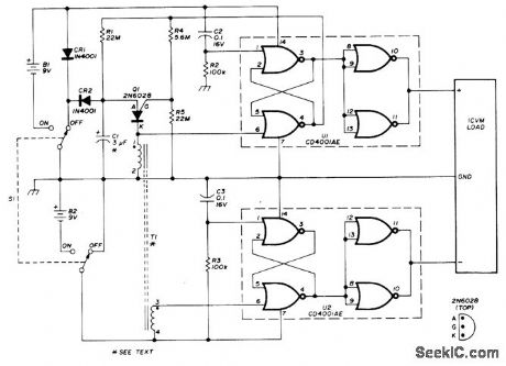
Tums off battery-powered IC VTVM automatically about 3.5 min aftertuning on with S1, to prolong battery life even though user forgets to tum off instrument. Circuit can be retriggered at any time in timing cycle by switching S1 off and then on again. Q1 is programmable UJT that drives latch using two gates of CD4001AE quad N0R gate U1. With pin 3 high and pin 4 low, timing circuit and load are both turned off; battery drain by U1 is then only 0.001 μA. Values of R1 and C1 determine time interval, T1 is air-core pulse trans-former having 600 tums (No. 36 to 401 enamel for primary and same number wound over primary for secondary.-R. Hardesty, Tum-Off Timer for Portable Equipment, Ham Fladio,Sept. 1976, p 42-44. (View)
View full Circuit Diagram | Comments | Reading(720)
LT1580_CIRCUIT
Published:2009/7/16 21:30:00 Author:Jessie


Figure 1 shows a circuit designed to deliver 2.5 V from a 3.3-V source with 5 V available for the control voltage. Figure 2 shows the response to a load step of 200 mA to 4.0 A. The circuit is configured with a 0.33-μF ADJUST-pin bypass capacitor. The performance without this capacitor is shown in Fig. 3. The difference in performance is the reason for providing the ADJUST pin on the fixed-voltage devices. A substantial savings in expensive output decoupling capacitance can be realized by adding a small ceramic capacitor at this pin. (View)
View full Circuit Diagram | Comments | Reading(618)
PROJECTION_LAMP_VOLTAGE_REGULATOR
Published:2009/7/12 22:30:00 Author:May

Circuit will regulate RMS output voltage across lamp to 100 V ±2% for input voltages between 105 and 250 VAC. Light output of 150-W projection lamp is sensed indirectly for use as feedback to firing circuit Q1-Q2 that controls conduction angle of triac Q3. Light pipe, painted black, is used to pick up red glow from back of reflectorinside lamp, which has relatively large mass and hence has relatively no 60-Hz modulation.- Circuit Applications for the Triac, Motorola, Phoenix, AZ, 1971, AN-466, p 12. (View)
View full Circuit Diagram | Comments | Reading(1351)
PROSTHETIC_HAND_CONTROL_CIRCUIT
Published:2009/7/16 21:28:00 Author:Jessie

A proposed circuit for the control of an electromechanical prosthetic hand would derive electrical control signals from shoulder movements. The harness would contain a linear potentiometer (R1 in the figure), the resistance of which would be varied by shrugging the shoulder, as in the older mechanical system. The variable output voltage of the potentiometer would be fed to art attenuating potentiometer (R2), which would be set to scale the voltage to the range of shoulder movement. The scaled voltage would be fed to an analog-to-digital converter of the type used to control a bar-graph display. Either a linear or a logarithmic converter could be used, depending on the requirements of the user. Each digital output, in continuous or single-pulse mode, would be fed to a transistor switch, which would supply current to a solenoid or motor to actuate one of the prosthetic fingers. With no shrug, the prosthetic thumb and all of the prosthetic fingers would be extended. As the shrug is increased, the digital outputs would turn on in sequence, thereby causing the thumb and fingers to move sequentially to the closed position. (View)
View full Circuit Diagram | Comments | Reading(1217)
TRANSFORMERLESS±12V_AT_15_mA
Published:2009/7/12 22:29:00 Author:May

Develaped to ρrovide bias voltage for six 741 opamps.Circuit connects ditectly across 120-V 60-Hz AC line.Article gives design procedure to meet performance requirements. For values shown, ripple is 1.1 V. Diode types are not critical.-C.Venditti, Build this Transformerless Low-Volt-age Supply, EDN Magazine, Feb. 5, 1977, p 102. (View)
View full Circuit Diagram | Comments | Reading(769)
POLARITY_PROTECTION_RELAY
Published:2009/7/16 21:28:00 Author:Jessie

A diode prevents the relay from applying power polarity is reversed. (View)
View full Circuit Diagram | Comments | Reading(573)
TEN_STEP_COUNTER_FOR_CONTROLLERS
Published:2009/7/12 22:29:00 Author:May

A 4017 divide-by-10 counter IC is the heart of this simple 10-output controller circuit. Two gates of a 4011 quad two-input NAND gate IC are connected in an astable oscillator circuit to clock the divide-by-10 counter U1. The step time is set by R5. With the RUN/RESET switch in the RUN position, U1 takes 10 equal steps and then stops. Momentarily switching S1 to RESET starts the cycle over (View)
View full Circuit Diagram | Comments | Reading(2905)
SYMBOL_GENERATOR
Published:2009/7/16 21:27:00 Author:Jessie

Combines sine and cosine waves of ten harmonic generators to produce X and Y waveforms for alphanumeric character generator.-K. E. Perry and E. J. Aho Radar-Computer Traces Alphanumeric Characters, Electronics, 34:26, p 75-79. (View)
View full Circuit Diagram | Comments | Reading(707)
TRIAC_ac_VOLTAGE_CONTROL
Published:2009/7/16 21:27:00 Author:Jessie

By using a variable resistor in the gate of TR1, variable conduction angles can be achieved via R1. (View)
View full Circuit Diagram | Comments | Reading(638)
CHARACTER_GENERATOR
Published:2009/7/16 21:26:00 Author:Jessie

Pulsed oscillator, used in producing alphanumeric display characters from combinations of circles, half-circles, and ellipses, is transient-free. Sinusoidal oscillator Q2 starts with full amplitude and stops in less than one cycle.-A. E. Popodi, Reliable Repertoire Of Display Circuits, Electronics, 38:2, p 60-66. (View)
View full Circuit Diagram | Comments | Reading(652)
Automatic trace phase shifting 90 circuit diagram
Published:2011/7/26 9:49:00 Author:Nancy | Keyword: Automatic trace, phase shifting

Figure 1 is a automatic trace phase shifting 90 circuit diagram. In the circuit, A1 is a buffer amplifier, which can amplify the input signal below 1 V into several volts. A2 is a phase shifting circuit with stable gain, the amplitude of the output signal is not relevant to the input frequency, it only changes the phase, so it is also called all pass filter.
The necessary condition to get 90 ° phase difference is RG=1/2πfC1, here we use servo circuit to control the RG. The synchronous detection circuit is formed by the analog multiplier, the output Uo of the synchronous detection circuit is equal to Ucosφ under the condition of 90° phase detection, which means it is not relevant to the amplitude of the input signal, the output Uo is equal to zero as long as the φ is equal to 90°. The integrator is also a servo circuit which uses VT1 to increase the output current. (View)
View full Circuit Diagram | Comments | Reading(593)
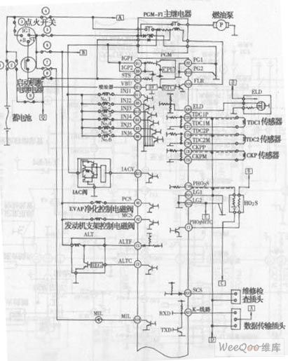
Yage Sedan V6 Engine Electronic Control System Circuit (the 1st)
Published:2011/7/18 2:57:00 Author:Felicity | Keyword: Yage Sedan, V6 Engine, Electronic Control System, Circuit, (the 1st)
View full Circuit Diagram | Comments | Reading(739)
_5_V_AT_200_mA_OR_7_20_V_AT_100_mA
Published:2009/7/16 21:26:00 Author:Jessie

Uses National LM741 opamp as noninverting follower to sample output of voltage divider and drive common terminal of National LM340-05 three-terminal voltage regulator. Heatsink tab of regulator U1 must be connected to floating heatsink, BR1 is Adva bridge.-H. Olson, Second-Generation IC Voltage Regulators, Ham Radio, March 1977, p 31-37. (View)
View full Circuit Diagram | Comments | Reading(672)
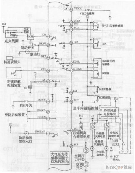
Yage Sedan 4-cylinder Engine Control System Circuit (the 1st)
Published:2011/7/18 3:02:00 Author:Felicity | Keyword: Yage Sedan, 4-cylinder Engine Control System, Circuit, (the 1st)
View full Circuit Diagram | Comments | Reading(744)
TUBE_AMPLIFIER_ISOLATES_HIGH_VOLTAGES
Published:2009/7/16 21:26:00 Author:Jessie

This amplifier can transfer dc-to 5-MHz signals across a potential difference of 25000 V. This circuit can be used in CRT displays, high-voltage applications, etc. Notice that the tube must be shielded because the tube will generate X-rays. Typically, about 0.1 -thick sheet metal would be used. (View)
View full Circuit Diagram | Comments | Reading(906)
UNBLANKING_PULSE_GENERATOR
Published:2009/7/16 21:25:00 Author:Jessie

Unblanking signal is produced by repeated amplification and clipping of 500-cps signal from antenna synchro driver. Square-wave output is applied to control grid of display cut. Balancing controls are adjusted so unblanking strobe line starts from confer.-R. T.Wolfram, Improved Communications Using Groundscatter Propagation, Electronics, 33:44, p 74-78. (View)
View full Circuit Diagram | Comments | Reading(694)
POWER_SUPPLY_MONITOR_MEMORY_PROTECTOR
Published:2009/7/16 21:25:00 Author:Jessie

This circuit detects low-voltage supply conditions, down to 0.6 V. D1 sets the trip point of the circuit. The circuit is useful to protect memory circuits from accidental writes in the event of power-supply lowvoltage conditions, which cause other circuits to turn off, etc. Response time is about 700 ns. R6 provides some hysteresis to ensure clean transitions. (View)
View full Circuit Diagram | Comments | Reading(553)
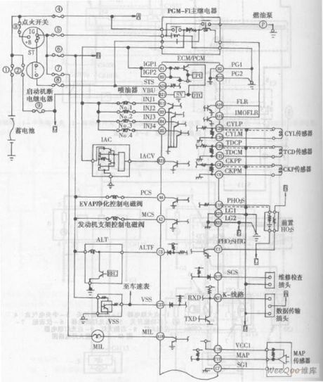
Yage Sedan 4-cylinder Engine Electronic Control System Circuit
Published:2011/7/18 3:06:00 Author:Felicity | Keyword: Yage Sedan, 4-cylinder Engine, Electronic Control System, Circuit
View full Circuit Diagram | Comments | Reading(788)
_15_V_AND__6_V_TRANSFORM_ERLESS
Published:2009/7/16 21:25:00 Author:Jessie

Transistorized regulator provides good voltage regulation with low ripple. Second ground prong is connected through fuse to grounded center conductor of AC line to guard against faulty AC wiring. If wiring is reversed, fuse will disable power supply and neon fault indicator will come on. At currents up to 55mA, -6 V output had 0.1-V ripple and +15 V output had 0.05-V ripple. - D. Kochen, Transformerless Power Supplies, 73 Magazine, Sept.1971, p 14-17. (View)
View full Circuit Diagram | Comments | Reading(576)
| Pages:750/2234 At 20741742743744745746747748749750751752753754755756757758759760Under 20 |
Circuit Categories
power supply circuit
Amplifier Circuit
Basic Circuit
LED and Light Circuit
Sensor Circuit
Signal Processing
Electrical Equipment Circuit
Control Circuit
Remote Control Circuit
A/D-D/A Converter Circuit
Audio Circuit
Measuring and Test Circuit
Communication Circuit
Computer-Related Circuit
555 Circuit
Automotive Circuit
Repairing Circuit