
Circuit Diagram
Index 749
POPULAR_VOLTAGES_SUPPLY
Published:2009/7/16 21:38:00 Author:Jessie

Provides most common fixed voltages required for transistor and IC projects. Eliminates cost and nuisance of replacing batteries. Provides t15 V at 100mA, +5 V at 1 A, and choice of +6.0, +8.2, and +12.0 V at 1 A. Separate grounds (not chassis grounds) permit connecting supplies in series to get combination voltages. Rectifier diodes are 100 PIY at 1 A. Use meter and shunt to give full scale at 1 A; for 150-mA meter, use 0.08 ohm for R1 (six 0.5-ohm resistors in parallel). U1 is LM340K-12, U2 is LM340K-8, U3 is LM340K-6, U4 is LM340K-5, and U5 is 4195.-C.J. Appel, A Combination Fixed-Voltage Supply, QST, Nov. 1977, p 36-37. (View)
View full Circuit Diagram | Comments | Reading(769)
HIGH_VOLTAGE_POWER_SUPPLY
Published:2009/7/16 21:38:00 Author:Jessie

This circuit uses a transformer to generate a high-voltage output (up to 20,000 V) from just four C cells. T1 can be a 50 to 100:1 turns ratio unit or can be made from a flyback transformer from a junked B/W TV. (View)
View full Circuit Diagram | Comments | Reading(0)
PATHFINDER
Published:2009/7/16 21:37:00 Author:Jessie

This circuit is little more than a simple two-transistor oscillator (a relaxation type) whose frequency is controlled by a light-dependent resistor (LDR). The oscillator can be built using nearly any NPN and PNP transistor combination desired, and its operation is simple, as its parts count is low. The resistance of R1 and the value of C1 determine the oscillating frequency of the circuit, which varies from a slow tick in darkness (when R1 is about 100,000 Ω) to a high-pitched tone in bright light (when R1 is 1000Ω). The change in frequency is heard through the transducer (BZ1). Power for the circuit is furnished by a single 1.5-V AA battery; because the Pathfinder draws so little power, it will function normally until the battery voltage drops to about 0.9 V. (View)
View full Circuit Diagram | Comments | Reading(1914)
LASER_RECEIVER_PHOTOMULTIPLIER_TUBE_SUPPLY
Published:2009/7/16 21:37:00 Author:Jessie

The figure shows the circuit diagram of a regulated 1000-Vdc power supply driven from a 12-Vdc source. A low-voltage secondary regulated power source supplying power to the PMT video pre-amplifier is included. Again, follow the caution regarding PMT power supplies. All precautions must be observed when working with the PMT high-voltage supply. (View)
View full Circuit Diagram | Comments | Reading(2586)
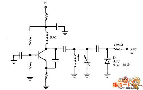
AFC varactor diode circuit diagram in this oscillator
Published:2011/7/20 4:55:00 Author:nelly | Keyword: AFC varactor diode, oscillator
View full Circuit Diagram | Comments | Reading(2199)
CRT_NUMBER_GENERATOR
Published:2009/7/16 21:35:00 Author:Jessie


Lissajous patterns on crt form numerals 0 to 9 that appear to be handwritten. Vertical and horizontal waveshapes used to produce a number are continuously applied to pair of number gates. Gates open whom excited by high-voltage r-f transformer, permitting waveforms to pass through to crt defection plates and create problem on screen. All waveshapes are derived from 60-cps centertapped sine-wave source. Reliability is insured through use of passive elements (resistors, capacitors, and diodes) and standard techniques of dipping, limiting, and/or phase shifting to generate required waveshapes.-R. L. White, Forming Handwritten. Like Digits on CRI Display, Electronics,32:11, p 138-140. (View)
View full Circuit Diagram | Comments | Reading(915)
Bile Former Grade Power Circuit
Published:2011/7/17 23:37:00 Author:Felicity | Keyword: Bile Former Grade, Power Circuit

View full Circuit Diagram | Comments | Reading(658)
5_V_MICROPOWER_LINEAR_REGULATOR
Published:2009/7/16 21:35:00 Author:Jessie

In battery systems where high load current is required intermittently and the system must remain in standby mode between uses, a linear regulator with micropower quiescent current and shut-down capability is needed. These situations arise in powering laptop disk drives, portable radio transmission modems, and peripheral motors, which are intermittently used. The LT1529 has 3 A current capability, 50 μA quiescent current, and just 16μA shutdown current. As shown in the circuit and chart, the LT1529-5 is a low-component-count solution with a very low dropout voltage of 0.6 V at 3-A output current. This low dropout is ideal for battery-powered systems in which extracting the maximum energy from the battery is important. In dropout, the output voltage will decrease smoothly, following the input. The quiescent current of the LT1529 increases only slightly in dropout, unlike the situation with many other low-dropout PNP regulators. (View)
View full Circuit Diagram | Comments | Reading(781)
BIOLOGICAL_SIGNAL_WAVEFORM_GENERATOR
Published:2009/7/16 21:35:00 Author:Jessie

The circuit operates as follows: U1A and U1B form a triangle waveform generator, using R6 to offset the output so that it is a positive-going signal. The amplitude is set by R2 and R3, and the ramp's rate of rise is set by R1 and C1. Using the values shown, the output has an amplitude of >1 V with rise and fall times of 0.5 ms, giving a total zeta duration of 1 ms. U1C provides an inverted output of U1B. When the RESET pin on U3 is triggered, its Q1 output goes low and the short is removed across C1 by one half of the analog switch (U4). At this time, the output of U1A will be negative and the output of U1B will start to ramp up. During this time, the output of the circuit is taken from U1B via the other half of the analog switch. When the ramp reaches its positive voltage threshold, the output of U1A goes positive and U1B will start to ramp down. The output of U1A is taken via U2A and U2B (both inverting Schmitt triggers with special input circuitry that protects the input from negative voltages and allows them to level-shift) to the CLOCK input of U3. It is also taken to the analog switch, which now takes the output of the circuit from U1C (which has an output ramping up from the negative maximum to 0V). At 0 V, the output of U1A will go negative, resulting in the Q1 output of U3 going high and again shorting C1. This produces 0V output until the next trigger input resets U3 and the cycle is repeated. (View)
View full Circuit Diagram | Comments | Reading(904)
HY8040 Typical Working Principle Circuit
Published:2011/7/18 4:54:00 Author:Felicity | Keyword: HY8040, Typical Working Principle, Circuit

View full Circuit Diagram | Comments | Reading(790)
12_V_LOW_RIPPLE
Published:2009/7/16 21:35:00 Author:Jessie

Three-transistor feedback circuit gives low-cost voltage stabilizer in which ripple is low and regulated output is very little less than unstabilized input voltage.-R. H. Pearson, Novel 5-Watt Class A Amplifier Uses Three-Transistor Feedback Circuit, Wireless World, March 1974, p 18. (View)
View full Circuit Diagram | Comments | Reading(1161)
_5_V_WITH_UNREGULATED__15_V
Published:2009/7/16 21:34:00 Author:Jessie

Developed for use with audio decoder that converts BCD output of digital display to audio tones that can be recognized by blind radio operator or experimenter.-D. R. Pacholok, Digital to Audio De-coder, 73 Magazine, Oct. 1977, p 178-180. (View)
View full Circuit Diagram | Comments | Reading(609)
McIntosh C22 Phono Pre-amp Circuit
Published:2011/7/18 3:08:00 Author:Felicity | Keyword: McIntosh C22 Phono Pre-amp Circuit

View full Circuit Diagram | Comments | Reading(5819)
ONE_CELL_CONVERTER
Published:2009/7/16 21:33:00 Author:Jessie

The regulator generates a 5-V output from a single lithium-ion cell. Initially, the lithium-ion cell is at 4.2 V, which is greater than the 3.75-V undervoltage-lockout (UVL) limit of the LM2587 Simple Switcher. Once it starts up, the boost circuit will continue to regulate-even when the battery voltage drops lower than the UVL limit. The level that the input voltage can drop to depends on the maximum load current desired. Of course, the source can be any type of battery-three alkaline, four NiCd, or even two lithium batteries. When power is applied to the circuit, the 10-kΩ resistor charges up the 47-μF input capacitor and supplies the startup current to the LM2587. After startup, the LM2587 input and the input capacitor draw current frorrt the switch node through the 1N914B boot-strap diode. When that happens, the IC input pin gets charged up to the output voltage minus a diode drop. In the circuit, with a 5-V output, the IC input voltage is 4.5 V after startup. It stays at 4.5 V-even when the input voltage drops to below 3.75 V. The input voltage can drop to 1.25 V when the regulator is supplying 250 mA. At 2.4 V, the regulator is 84 percent efficient if the 1N914B bootstrap diode is replaced with a 1N5817 Schottky diode. (View)
View full Circuit Diagram | Comments | Reading(2113)
3_IN_1_TEST_SET_LOGIC_PROBE_SIGNAL_TRACER_AND_INJECTOR
Published:2009/7/16 21:31:00 Author:Jessie

This circuit for a test set contains a signal injector (U1A/U1B) and associated components, a logic probe (U1C) and an audio amplifier. S1 selects either 10-kHz or 100-Hz output. U1D, U1E, and U1F form an audio amplifier that drives a piezo sounder element without an internal driver so that it functions as a piezoelectric speaker.
(View)
View full Circuit Diagram | Comments | Reading(1495)
TWO_FUNCTION_CONTROLLER
Published:2009/7/12 22:32:00 Author:May

This two-function controller operates a motor when started, then energizes a solenoid, relay,etc., when stopped. (View)
View full Circuit Diagram | Comments | Reading(927)
CUT_PHONE_LINE_ALARM_1
Published:2009/7/12 22:31:00 Author:May

Detecting a cut phone line can be an important function of an electronic security system. UnforLunately, detecting a cut phone line isn't easy because the voltages on a normal phone line vary so rnuch. The voltage is typically 48 Vdc when the telephone is on the hook, 2 to 15 Vdc during a conversation, 90 Vac during ringing, and 200 Vdc when the telephone company is testing the line. Brief moments of 0 V are common; what you really want to detect is a voltage that goes to zero and stays there. A second restriction is that the cut phone line detector cannot draw any appreciable current. Its impedance has to be higher than 50 MΩ or the telephone company will think it's a leaky cable, Components R1, R2, R3, and C1 smooth out momentary variations in voltage so that the alarm doesn't trigger every time the telephone rings. If the voltage stays at zero for 30 s or more, the alarm should trigger. The load can be a piezo buzzer, an optocoupler, or a small relay.Because of the tiny currents it rnust detect, this circuit should be powered by its own 9-V battery, with no direct connection to the rest of the burglar alarm. Otherwise, a slight difference in ground potentials might cause the circuit to perform somewhat erratically. (View)
View full Circuit Diagram | Comments | Reading(1074)
Yage Sedan V6 Engine Electronic Control System Circuit (the 2nd)
Published:2011/7/18 2:59:00 Author:Felicity | Keyword: Yage Sedan V6 Engine Electronic Control System Circuit (the 2nd)
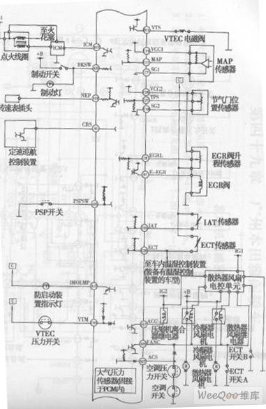
View full Circuit Diagram | Comments | Reading(877)
SPARK_MACHINING_CONTROL
Published:2009/7/12 22:31:00 Author:May

Servo-controlled high-power electric spark machine produces repeated discharges between tool electrode and workpiece to cause erosion of metal to desired shape. Power source is 4.5-KV three-phase rectifer providing peak discharge current of 4,500 amp at pulse repetition rate of 2,880 pps. Rotary gap is used for pulse switching.-E. M. Williams and C. P. Porterfield, Spark Machine Tool has Servo Control, Electronics, 31:43, p90-92. (View)
View full Circuit Diagram | Comments | Reading(1289)
FOUR_OUTPUT_CONTROLLER
Published:2009/7/12 22:31:00 Author:May

This controller offers up to four timed outputs that can be used to operate motors, air valves, solenoids, relays, etc. The timer sections are cascaded so that as one timer times out, it triggers the next timer, and so on, until the last timer times out. The intended application for the controller required a two-sensor input that would start only when both inputs occur simultaneously. Note, however, that the start-signal logic could be modified to accommodate a combination of any number of input sensors, or even a single switch closure. The controller also includes an inhibit circuit that keeps the sequence from restarting before a cycle is completed. (View)
View full Circuit Diagram | Comments | Reading(1174)
| Pages:749/2234 At 20741742743744745746747748749750751752753754755756757758759760Under 20 |
Circuit Categories
power supply circuit
Amplifier Circuit
Basic Circuit
LED and Light Circuit
Sensor Circuit
Signal Processing
Electrical Equipment Circuit
Control Circuit
Remote Control Circuit
A/D-D/A Converter Circuit
Audio Circuit
Measuring and Test Circuit
Communication Circuit
Computer-Related Circuit
555 Circuit
Automotive Circuit
Repairing Circuit