
Circuit Diagram
Index 595
DUAL_LIMIT_DETECTOR
Published:2009/7/14 22:07:00 Author:Jessie

Provides 12-V output when applied DC input signal exceeds reference high limit established by setting of R1 or falls below reference low limit established by setting of R2. When input drops below low limit, CA3080 changes CA3094 to high-output condition. Output is low in voltage window between limits (dead zone).-E. M. Noll, Linear IC Principles, Experiments, and Projects, Howard W. Sams, Indianapolis, IN, 1974, p 317-318. (View)
View full Circuit Diagram | Comments | Reading(779)
ELECTRONIC_LOCK
Published:2009/7/14 22:06:00 Author:Jessie

Correct combination of switches S1-S5 must be actuated to energize relay in series with ignition switch of auto or any other type of electric lock. If wrong combination is used, lock cannot be opened until resetting combination is entered,When car ignition is turned off, ignition relay should be reset (contact opened) by pressing S6.With connections shown, switches S2,S4,andS5 must be depressed simultaneously to oρen (set) lock. If error is made, output of fault gate goes to logic 1 and contacts of relay 2 will open, After error, S1 and S3 must be depressed simultaneously to reset lock before opening combination can be used again. Switches can be connected for any other desired combinations.-L. F. Caso, Electronic Combination Lock Offers Double Protection, Electronic, June 27, 1974, ρ 110; reprinted in ″Circuits for Electronics Engineers,″Electronics,1977, p 346. (View)
View full Circuit Diagram | Comments | Reading(1675)
WINDOW_DETECTOR
Published:2009/7/14 22:05:00 Author:Jessie

Connections shown for 322 comparators give high output only when input voltage is between thresholds set by R2 and R3 (within voltage window). Output of circuit goes low whenever input is below threshold 1 or above threshold 2.-W. G. Jung, IC Timer Cookbook, Howard W. Sams, Indianapolis, IN, 1977, p 153. (View)
View full Circuit Diagram | Comments | Reading(2525)
DIGITAL_MAGNETIC_CORE_DIVIDER
Published:2009/7/14 21:37:00 Author:May

Frequency-divider chain uses pairs of rectangular hysteresis-loop magnetic cores as counting elements. Has high accuracy and stability. First core (ladle) is driven to saturation by each input pulse. Constant-voltage integral output from ladle core drives second bucket core. With appropriate turns ratios of windings, bucket core can be made to walk up its hysteresis loop in any number of predetermined steps. Successful single-stage dividers have been made up to scales of 17, with reliable operation from 10 to 50 kc.-A. Rose, Magnetic-Core Divider for ITV Sync Generators, Electronics, 31:15, p 76-77. (View)
View full Circuit Diagram | Comments | Reading(840)
SAFE_SWITCHING_OF_SOLENOIDS
Published:2009/7/14 22:05:00 Author:Jessie

Optoisolator provides protective interface between teleprinter and 8080A or other microprocessor when switching inductive loads of teleprinter RC filter across Darlington pair speeds release time of print magnets.-T. C. McDermott, Switching Inductive Loads with Solid-State Devices, Ham Radio, June 1978, p 99-100. (View)
View full Circuit Diagram | Comments | Reading(777)
DUAL_DELAY
Published:2009/7/14 21:37:00 Author:May

Two-transistor circuit produces pulses of finite width that start finite lime after reference pulse. Initial delay is determined by R1-R2-C1 and pulse width by C2-R4.-H. P. Brockman, Circuit Provides Dual Delay, Electronics, 32:18, p 62-65. (View)
View full Circuit Diagram | Comments | Reading(683)
MULTIRATE_VIDEO_SYNC_STRIPPER
Published:2009/7/14 22:04:00 Author:Jessie

This dual-comparator, multirate video sync stripper provides separate horizontal and vertical pulses that are consistent with the composite video-input-signal sync pulses. Using an LM319 dual-comparator integrated circuit and associated passive components, this circuit can strip horizontal (HSYNC) and vertical (VSYNC) sync pulses from standard RS170 video (525/2:1 interlaced) through an industry high-end video rate of 1280 X 1024/1:1 (noninterlaced). The composite video input signal is ac-coupled through capacitors C1 and C2 to the junction of resistors R2 and R3 and diode CR1. The video sync tips are clamped by CR1 at approximately 4.5 V and applied to noninverting input of comparator U1A (pin 4). Positive feedback from resistors R6 and R3 provides a hysteresis of about l50μV to ensure a stable state change at the output of U1A (pin 12). R8 and C5 constitute a low-pass filter that prevents the filtered amplitude of the horizontal sync pulse from dropping below the threshold volt-age of 7.5 V, established by R10 and R11 for the inverting input of U1B (pin 10). R9 and R12 supply a hysteresis of about 15 mV to the noninverting input of U1B (pin 9). The inherently longer vertical sync pulse width provides sufficient time for U1A (pin l2) to be near ground. As a result C5 is adequately charged Lo exceed the threshold voltage and generate a vertical (VDRIVE) at U1B (pin 7). (View)
View full Circuit Diagram | Comments | Reading(3207)
10_DIGIT_CODED_SWITCH
Published:2009/7/14 22:03:00 Author:Jessie

Uses seven Texas Instruments positive-logic chips,NAND gates 1-4 and 5-8 are from two SN7400N packages, Two SN7404N packages each provide six of inverting opamps shown Desired coda is set up as combination of 0s and 1s byρresetting ten 2-position switches. To open lock, switches at input for 0 and 1 must be pushed in Sequence of code Arrangement gives 1024 possible combinations but provides much greater protection unless intruder knows that 10 digits are required. Article describes operation of circuit. One requirement of the 2N7496N shift registers is that information be present at serial input before clocking pulse occurs.-K. E. Potter, Ten-Digit Code-Operated Switch or combination Lock, Wireless World, May 1974, P 123. (View)
View full Circuit Diagram | Comments | Reading(1370)
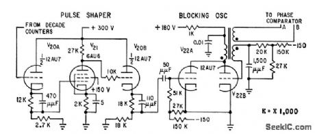
FLOWMETER_FREQUENCY_CONVERTER
Published:2009/7/14 22:01:00 Author:Jessie
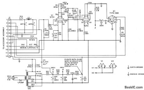
Provides output signal that is directly provides output signal that is directly proportional to frequency of input from ,turbine flow-sensing element, for driving associated electronic potentiometer. V1 and V2 form three-stage limiting amplifier. Capacitor tachometer circuit uses chopper K1 to discharge C5 repetitively through adjustable-range resistor. Adjustable precision resistor in series with slide-wire of potentiometer provides accurate manual compensation for changes in specific gravity of measured medium. Circuit is Potter model 11-B frequency converter.-G. C. Carrol, Industrial Instrument Servicing Handbook, McGraw-Hill, N.Y., 1960, p 3-3. (View)
View full Circuit Diagram | Comments | Reading(831)
3_kHz_TONE_LOCK
Published:2009/7/14 22:00:00 Author:Jessie

Electric door lock opens only when signal voltage of about 3 kHz is applied to two exposed terminals by holding compact single-IC AF oscillator against terminals. Will not respond to DC or 60-Hz AC. Pocket oscillator operates from 9-V transistor radio battery, with current drawn only when output prongs are held against lock terminals,SCR can be any type capable of handling current drawn by electric lock. -J. A. Sandler, 11 Projects under $11, Modern Electronics, June 1978, p 54-58. (View)
View full Circuit Diagram | Comments | Reading(705)
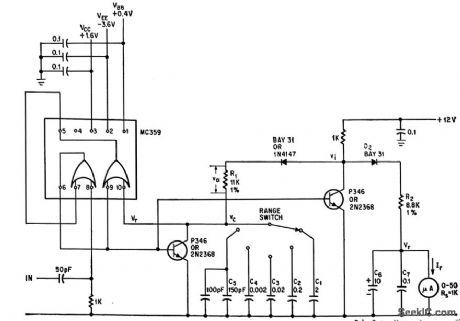
I_F_BESS_DIGITAL_FREQUENCY_METER
Published:2009/7/14 22:00:00 Author:Jessie
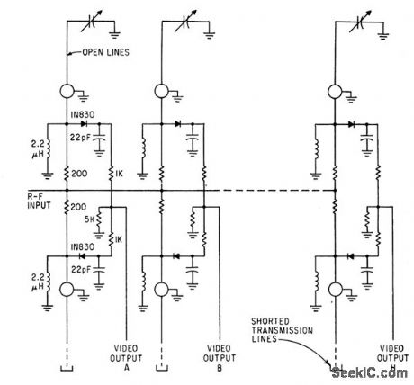
Binary Electromagnetic Signal Signature (bess) concept permits measuring frequency of single r-f pulse in range of 55 to 65 Mc. Eight pairs of Iransmission lines divide this band into eight equal segments of 1.25 Mc. Same con cope con be applied to other ranges up to 4,000 Mc.-R. F. Morrison, Jr., and M. N. Sarachan, Binary Frequency Sensing Measuresa SinglePulse, Electronics, 36:14, p 42-46. (View)
View full Circuit Diagram | Comments | Reading(685)
CABLE_PROPAGATION_DELAY_TIME
Published:2009/7/14 22:23:00 Author:Jessie
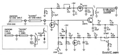
Pulse generated by tunnel diode travels to end of 50-ohm cable, is reflected back, and retriggers tunnel diode to repeal process. Resulting repetition rate of pulses, measured with circuit feeding frequency meter, gives delay time with high accuracy. Transformer (lower left) permits measuring cables of other impedances.-P. J. Kindlmann, Tunnel-Diode Pulser Measures Cable Delay,Electronics,39:4,p 87-88. (View)
View full Circuit Diagram | Comments | Reading(1171)
LINE_OPERATED_DELAY
Published:2009/7/14 22:23:00 Author:Jessie

Operates directly from 117V a-c line to provide time delays adjustable from 8 millisec to 5 sec for lamp loads up to 100 w.-D. V. Jones, Quick-0n-The-Trigger Design. Electronics.38:12,p105-110. (View)
View full Circuit Diagram | Comments | Reading(657)
VARIABLE_DELAY_FOR_ANALOG_SIMULATION
Published:2009/7/14 22:21:00 Author:Jessie


Uses thick-walled ferrite cores to store voltage levels as flux levels.-W. C. Till and W. H. Ko. Versatile Analog storage uses ferrite Cores. Electronics.35 39,P60-63 (View)
View full Circuit Diagram | Comments | Reading(561)
SOLID_STATE_DELAY_WITH_A_C_OUTPUT
Published:2009/7/14 22:19:00 Author:Jessie

Timing sequence is initiated by switch, which applies power to ujt circuit. When emitter voltage of vie reaches peak point, C1 remains charged and vie oscillates at high frequency. Resulting pulses turn on scr’s through pulse transformer, applying voltage to load.- Transistor Manual, Seventh Edition, General Electric Co.1964, p 322. (View)
View full Circuit Diagram | Comments | Reading(1831)
SCR_CONTROLS_RITY_MOTOR
Published:2009/7/14 22:18:00 Author:Jessie
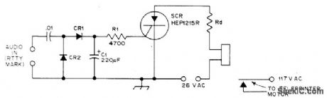
Single SCR can replace several transistor or tube stages in RTTY, VOX, COR, and other relay control circuits. Threshold triggering effect of SCR means triggering is automatically suppressed on low-level noise and similar interference. Used in RTTY autostart and motor delay sections of demodulator. Pickup time is 1 s and dropout time is 3 s, determined by values of R1 and C1 and by SCR, Circuit keys only on 2125-Hz mark tone. Diodes are 50-PlV silicon. Rd is appropriate dropping resistor for relay, if needed.-D, Weeden, SCR Relay Control for RTTY, VOX, and COR ,QSTT, July 1976, p 42. (View)
View full Circuit Diagram | Comments | Reading(1486)
10_W_SINGLE_ENDED_PUSH_PULL_OUTPUT
Published:2009/7/14 22:18:00 Author:Jessie

Feeds voice coil directly, making output transformer unnecessary. First preamplifying stage has positive feedback to point ofoscillation, while amplifier and output stages have negative feedback. Circuit haslow distortion, fiat response, and only a few degrees of phase shift over audio range.-J. Rodrigues De Miranda, Push. Pull Amplifiers Drive Speaker Directly,Electronics, 31:29, p 76-79. (View)
View full Circuit Diagram | Comments | Reading(1103)
Q_MULTIPLIER
Published:2009/7/14 22:15:00 Author:Jessie
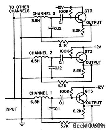
Circuit shows three channels of multi-channel selective a-f ampliler(190, 216.5, and 235 cps) using various coil-capacitor combinations with transistorQ multiplier to provide staggered resonant frequencies. Used in frequency- selectiye calling systems.-G. B. Miller, Transistor Q Multiplier for Audio Frequencies,Electronics, 31:19, p 79-81. (View)
View full Circuit Diagram | Comments | Reading(0)
COMPLEMENTARY_SYMMEIRY_AUDIO_AMPLIFIER
Published:2009/7/14 22:14:00 Author:Jessie

Provides nearly maximum power theoreticallyavailable from single d-c supply.Distortion is low,large feedbacks, both a-c and d-c, make amplifier insensitive to unbalance of output transistors.-R. S. Richards, How to Design Transformerless Audio-Frequency Power Amplifers, Electronics, 35:46, p 50-52. (View)
View full Circuit Diagram | Comments | Reading(921)
PULSE_RATE_METER
Published:2009/7/14 22:12:00 Author:Jessie


Current pulse width is controlled by feedback voltage proportional to charge on output capacitor, to insure that each input pulse feeds exactly the same charge to the output circuit.-R. J. Smith-Saville and S. Ness, Charge Feedback Increases Pulse-Rate Meter Accuracy, Electronics, 39:3, p 85-86. (View)
View full Circuit Diagram | Comments | Reading(1051)
| Pages:595/2234 At 20581582583584585586587588589590591592593594595596597598599600Under 20 |
Circuit Categories
power supply circuit
Amplifier Circuit
Basic Circuit
LED and Light Circuit
Sensor Circuit
Signal Processing
Electrical Equipment Circuit
Control Circuit
Remote Control Circuit
A/D-D/A Converter Circuit
Audio Circuit
Measuring and Test Circuit
Communication Circuit
Computer-Related Circuit
555 Circuit
Automotive Circuit
Repairing Circuit