
Circuit Diagram
Index 582
Beijing Pajero SUV Engine Control System (M / T) Circuit (the 2nd)
Published:2011/8/1 2:54:00 Author:Felicity | Keyword: Beijing Pajero SUV, Engine Control System (M / T)
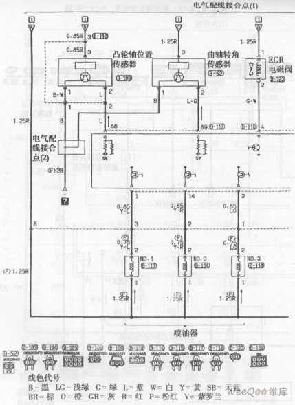
Wire color code
B=black LG=light green G=green L=blue W=white Y=yellow SB=sky blue BR= brown O=orange GR=gray R=red P=pink V=violet (View)
View full Circuit Diagram | Comments | Reading(787)
Beijing Pajero SUV Engine Control System (M / T) Circuit (the 3rd)
Published:2011/8/1 2:54:00 Author:Felicity | Keyword: Beijing Pajero SUV, Engine Control System (M / T), (the 3rd)
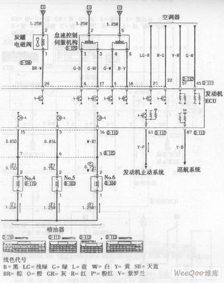
Wire color code
B=black LG=light green G=green L=blue W=white Y=yellow SB=sky blue BR= brown O=orange GR=gray R=red P=pink V=violet (View)
View full Circuit Diagram | Comments | Reading(769)
74 Series digital circuit of 74LS240,74F240 eight inverting buffer/line driver/ line receiver(three-state)
Published:2011/8/1 20:52:00 Author:Lucas | Keyword: 74 Series , digital circuit , eight inverting buffer, line driver, line receiver, three-state


When 1G and 2G are H at the same time, Y=high resistance;when 1G and 2G are L at the same time, Y=A.
(View)
View full Circuit Diagram | Comments | Reading(1043)
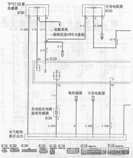
Beijing Pajero SUV Engine Control System (M / T) Circuit (the 4th)
Published:2011/8/1 2:43:00 Author:Felicity | Keyword: Beijing Pajero SUV, Engine Control System (M / T), (the 4th)
View full Circuit Diagram | Comments | Reading(767)
74 Series digital circuit of 74199 8-bit shift register
Published:2011/8/1 20:52:00 Author:Lucas | Keyword: 74 Series , digital circuit, 8-bit shift register


Parallel storage; right shift(direction is from the QA to QH): left shift(direction is from the QH to QA); it forbids the clock.a. .. h= the input of steady-state input level of A to H.QAo, QBo, QGo, QHo=the corresponding level level of QA, QB, QG, QH before building the specified steady state.QAn, QBn..QGn= the corresponding level of QA, QB to QGbefore the next jump of the clock.
(View)
View full Circuit Diagram | Comments | Reading(1209)
74 Series digital circuit of 74196/74197 preset decimal/binary counter
Published:2011/8/1 20:53:00 Author:Lucas | Keyword: 74 Series, digital circuit , preset decimal counter, binary counter


196 can make BCD binary/quinary count, and 197 is the binary counter.
(View)
View full Circuit Diagram | Comments | Reading(1733)
74 Series digital circuit of 74160/161/162/16 synchronous 4-bit counter
Published:2011/8/1 20:53:00 Author:Lucas | Keyword: 74 Series , digital circuit , synchronous 4-bit counter


160 is the decimal counter, which can direct remove; 161 is the binary counter, which can direct remove; 162 decimal counter can synchronous clear; 163 binary counter can synchronous clear. Two active-high inputs P and T allow dynamic counter to be easy to carry out the cascade; T allows dynamic binary output; if the counter is at a maximum state in the allowing state, the dynamic binary output will go high.
(View)
View full Circuit Diagram | Comments | Reading(3126)
Hyundai Sonata Car Cruise Control Circuit (the 1st)
Published:2011/8/1 2:43:00 Author:Felicity | Keyword: Hyundai Sonata Car, Cruise Control
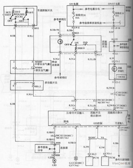
View full Circuit Diagram | Comments | Reading(1040)
Charger for Motor Vehicle Storage Battery (the 3rd)
Published:2011/7/29 4:21:00 Author:Felicity | Keyword: Charger, Motor Vehicle, Storage Battery
Work of the circuit
The circuit consists of power circuit, pulse oscillator and charging controlling circuit. (It is showed in picture 7-148.)
Power circuit consists of power transformer T, the normally closed contacts K2 relay, normally open contacts of relay Kl, bridge rectifier, URl, UR2, voltage regulator diode VS, capacitor CO, Cl, resistors RO, Rl, fuse FUl, indicating light HL and ammeter PA.
Pulse oscillator consists of time-base integrated circuit IC, potentiometer RPl and related peripheral components.
Charging controlling circuit consists of thyristor VT, relay K2, potentiometer RP2 and peripheral components.
220V AC voltage is adjusted and produces +12V voltage. It works as the working voltage of the pulse oscillator. When the OSC is working, the pulse of IC controls the working condition of relay K1. When the pulse OSC outputs low electrical level, GB is charged. At the same time, the light HL is lightened. When the pulse OSC outputs high electrical level, GB is not charged. And the light HL stops shining. When GB is not fully charged, the indicating light VL does not shine. But when GB is fully charged, VL shines to show that charging is done. (View)
View full Circuit Diagram | Comments | Reading(745)
Automotive Braking Air Under Pressure Protector One
Published:2011/7/29 4:15:00 Author:Felicity | Keyword: Automotive Braking, Air Under Pressure Protector
Work of the circuit
The circuit consists of control implementation circuit, low-frequency oscillator, audio oscillator, the pressure sensor SP, relay K and light and sound show circuit. (It is showed in picture 7-154.)
Control implementation circuit consists of relay K and clutch switch S2.
Low-frequency oscillator consists of time-base integrated circuit ICl, resistors Rl and R2 and capacitors Cl and C2.
Audio oscillator consists of time-base integrated circuit lC2, resistors R3 and R4 and capacitors C3 and C4.
Light and sound show circuit consists of resistor R5, light-emitting diodes VL and piezoelectric buzzer HA.
When the pressure of the reservoir is above the safe braking pressure, the contact inside pressure sensor SP releases and this protector doesn’t work.
When the pressure of the reservoir is under the safe braking pressure, the contact inside pressure sensor SP closes, and the low frequency and audio frequency oscillator are both at work (the low frequency oscillator modulate the audio frequency oscillator) to make VL shine and HA sends out alarm. At the same time , relay K closes , and the normally close contact releases to cut off the +12V power of the ignition system and the engine stops. (View)
View full Circuit Diagram | Comments | Reading(533)
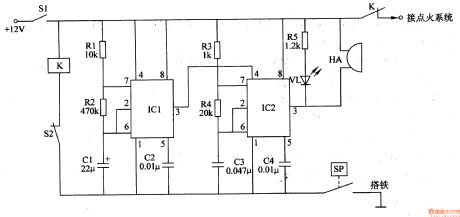
Automotive Braking Air Under Pressure Protector Two
Published:2011/7/29 4:00:00 Author:Felicity | Keyword: Automotive Braking, Air Under Pressure Protector
Work of the circuit
The circuit consists of air pressure sensor SPl, oil pressure sensor SP2, auto ignition switch Sl, clutch switch S2, buzzer HA, relay K, audio integrated circuit IC, transistor V, diode VDl-VD3, resistors Rl-R4, capacitors Cl and C2 and light HLl and HL2. (It is showed in picture 7-154.)
When the pressure of the braking air and the engine oil is normal, the contacts inside sensor SP1 and sensor SP2 releases. This circuit stands by.
When the pressure of the braking air and the engine oil is low, the contact inside sensor SP1 or sensor SP2 closes to make HL1 and VD2 or HL2 and VD3 on. And the relay K closes and the normally close contact cut off the +12V work power to extinguish the engine. At the same time IC works to make HA send out alarm. (View)
View full Circuit Diagram | Comments | Reading(575)
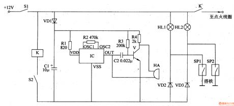
Automotive Braking Air Under Pressure Protector Three
Published:2011/7/29 3:58:00 Author:Felicity | Keyword: Automotive Braking, Air Under Pressure Protector
Work of the circuit
The circuit consists of speaker BL, voltage indicator HL, self-excited audio oscillator, the clutch switch S1, S2 and pressure sensing ignition switch S3. (It is showed in picture 7-155.)
Self-excited audio oscillator consists of power electronic switch IC IC (includes regulator, zoom, comparator, select 'pass to the ignition coil, plastic and power output and other circuits) and the resistors Rl and R2, capacitor C.
This automotive braking air under pressure protector consists of speaker BL, under pressure indicator HL, audio oscillator, clutch switch S1, ignition switch S2 and air pressure sensor switch S3.
When the braking pressure is normal, the contact inside S3 releases and this protector doesn’t work.
When the braking pressure is low, the contact inside S3 closes to make K closes too. And the normally close contact releases to cut off the power of the ignition system and the engine stops. At the same time, the under pressure indicator HL is on; the self-excited audio oscillator works; the speaker BL sends out alarm. (View)
View full Circuit Diagram | Comments | Reading(504)
Automotive Braking Air Under Pressure Protector Four
Published:2011/7/29 3:48:00 Author:Felicity | Keyword: Automotive Braking, Air Under Pressure Protector
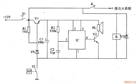
Work of the circuit
The circuit consists of pressure measurement and control circuit, voltage regulator filter circuit and voice alarm circuit. (It is showed in picture 7-156.)
Pressure measurement and control circuit consists of air pressure sensing switch S2, the ignition switch Sl, the relay K and diode VD.
Voltage regulator filter circuit consists of transistor Vl, resistors Rl, voltage regulator diode VS and filter capacitor Cl.
Voice alarm circuit consists of voice integrated circuit IC, resistor anal, capacitor C2, transistor V2 and the speaker BL.
When the braking pressure is normal, the contact inside S2 releases and this protector doesn’t work. The +12V power supplies for the ignition system through ignition switch S1 and the normally close contact of K.
When the braking pressure is below 25N/cm2, the contact of S2 closes to make K on. And the normally close contact releases to cut off the power of the ignition system and the engine stops. At the same time, after being regulated by V1, VS and smoothed by C1, the +12V voltage supplies IC for 3V direct work voltage. When IC is on, the vocal electrical signal output by pin 4 is amplified by V2 to drive BL to send out “Be care of the air pressure” voice. (View)
View full Circuit Diagram | Comments | Reading(525)
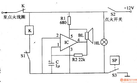
Drunken Driving Limiter (the 1st)
Published:2011/7/29 3:36:00 Author:Felicity | Keyword: Drunken Driving Limiter, the 1st

Work of the circuit
The circuit consists of power circuit, alcoholic testing circuit, amplifying circuit and trigger circuit. (It is showed in picture 7-160.)
Power circuit consists of current limiting resistor R4, Rl, and one end integrated voltage regulator IC3. +12V voltage is limited by R4. Then the voltage works as the working voltage of the trigger and signal amplifier circuit. The is limited by R1 and regulated by IC3. It then turns into +5V and supplied to the alcoholic testing circuit.
Alcoholic testing circuit consists of alcohol (ie ethanol) sensor components ICl and variable resistor RP.
Amplifying circuit consists of transistor Vl, V2 and resistors R2, R3.
Trigger circuit consists of time-base integrated circuit IC2.
When you turn on the switch the power circuit starts to work. When the alcoholic sensory package does not test the sense of alcohol, the car works without interference.
But if the driver is drunk IC1 tests, the sense of alcohol. The voltage of IC1 raises and the trigger is detonated. The high voltage circuit of the car is cut off. The driver cannot start the car. (View)
View full Circuit Diagram | Comments | Reading(608)
Eye-care Lamps (the 3rd)
Published:2011/7/29 3:29:00 Author:Felicity | Keyword: Eye-care Lamps

Work of the circuit
The circuit consists of power switch S1, rectifier diode V1-V4, resistor R1,R2, light-sensitive resistor RG, potentiometer RP, controlling switch S2, capacitor C and light EL (It is showed in picture 9-70.).
Turn on power switch S1 and EL is lightened. When the environmental light is strong, light of EL will become weak. When the environmental light is weak, light of EL will become strong
Put switch S2 in site 1 and the circuit is controlled by people. We can change the value of RP to change the light intensity of the lamp. (View)
View full Circuit Diagram | Comments | Reading(1113)
Voltage-controlled oscillator (NE566V) circuit can be controlled in the wide range
Published:2011/8/8 8:03:00 Author:nelly | Keyword: Voltage-controlled, oscillator, wide range

Voltage-controlled oscillator (NE566V) circuit can be controlled in the wide range . (View)
View full Circuit Diagram | Comments | Reading(686)
Memory Strengthener (the 1st)
Published:2011/7/29 3:02:00 Author:Felicity | Keyword: Memory Strengthener

Work of the circuit
The circuit consists of low-frequency Oscillator, negative feed-back amplifier, mike BM, converting switch S and earphone jack XS. (It is showed in picture 9-75.).
Low-frequency Oscillator consists of six non-gate IC IC (Dl-D6) within the non-gate D5, D6 and resistor R3, capacitor C2.
Negative feed-back amplifier consists of the Dl-D4 within IC and resistor R2.
If you want to use it as a hearing-aid or memory strengthener, you should put S in site 1. Here BM turns the sound signal it collects into electric signal which drives BE to make sound after being adjusted.
If you want to use it as a hypnotizer you should turn S to site 2. Here the signal produced by low-frequency Oscillator will turn to the sound.The sound makes people sleepy after being amplified by negative feed-back amplifier. (View)
View full Circuit Diagram | Comments | Reading(647)
The logic high and low LEV LED digital display circuit
Published:2011/8/3 23:23:00 Author:Seven | Keyword: logic, LEV, digital display

Here is to introduce the logic probe detector indicated by LED, the circuit is simple and direct, and it needs no debugging while manufacturing, the circuit is shown in figure 1. The circuit structure and working principle is shown in figure 1, IC 1(N1 and N2) is 6 phase reversers 7404, there are only 2. IC2 and relevant elements compose the dual steady circuit. The switch S1 composes the 555 dual steady reset circuit. LED1 and LED2 are 2 common positive digit tube.
(View)
View full Circuit Diagram | Comments | Reading(660)
The 3-channel audio power amplifier ICTA18H circuit
Published:2011/8/1 3:09:00 Author:Seven | Keyword: 3-channel, audio power amplifier
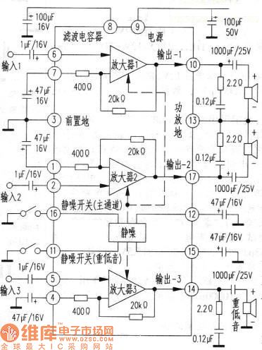
The IC working voltage is 10-30V. The limit output power is 50W(when the power supply is 20V and the impedance of the loudspeaker is 8Ω, there is 6W output power without any distortion). Figure 1 is the typical application of TA8218H. In the affiliated table are the pin functions and the tested data on Toshiba 2938XP(with Hangzhou U-201 multimeter, the R*100 gear). By the way, either of TA8218AH or TA8218AN can replace TA8218H.Figure 1. the typical application of TA8218H
(View)
View full Circuit Diagram | Comments | Reading(1515)
The driving circuit of proportional electromagnet
Published:2011/7/15 21:50:00 Author:Ariel Wang | Keyword: driving, proportional electromagnet

If you want to control the circuit,you can change duty ratio which is input to electrical signal of proportional electromagnet switch to realize controlling electric current. The more place the duty ration takes ,the faster of the controlling electric current goes through the coil of electromagnet.And the larger of the displacement . See chart 1 for the proportional electromagnet driveing circuit.
In driving circuit,R1 is current limiting resistor .It conducts IRL tube.D1 is a steering diode. It provides the right voltage direction for IRL3803 tube. Diode D2 is being the protective role.It avoids over voltage destroy proportional electromagnet.Proportional electromagnet is charged directly by 24V voltage.
(View)
View full Circuit Diagram | Comments | Reading(731)
| Pages:582/2234 At 20581582583584585586587588589590591592593594595596597598599600Under 20 |
Circuit Categories
power supply circuit
Amplifier Circuit
Basic Circuit
LED and Light Circuit
Sensor Circuit
Signal Processing
Electrical Equipment Circuit
Control Circuit
Remote Control Circuit
A/D-D/A Converter Circuit
Audio Circuit
Measuring and Test Circuit
Communication Circuit
Computer-Related Circuit
555 Circuit
Automotive Circuit
Repairing Circuit