
Circuit Diagram
Index 594
DIVIDER_ELIMINATES_COUNT_STARTING_JITTER
Published:2009/7/14 21:45:00 Author:Jessie
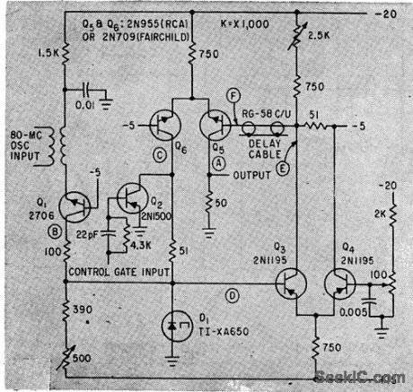
Output of 80-Mc free-running crystal oscillator is divided by 8 to give 10-Mc time base that is almost perfect square wave.-W.O. LeCroy, Jr., Eliminating One-Count Uncertainty in Cycle-Counting Interval Timers, Electronics, 35:29, p 46-47. (View)
View full Circuit Diagram | Comments | Reading(655)
SIMPLE_ALL_PASS_FILTER
Published:2009/7/14 21:53:00 Author:Jessie
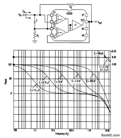

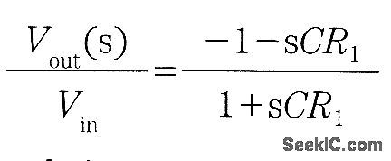
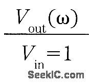
A very simple all-pass implementation can be realized with an active-feedback amplifier like the AD830 or the LTC1193. R1 and C set the filter’s actual transfer function, while R2 is needed to provide a purely real input impedance over the frequency range of the AD830 (necessary for measurement reasons). The filter’s two basic equations are and from which we can see that the magnitude is constant:and the phase of Vout/Vin as a function of ω is 180°-2 tan-1 (ωCR1)From the first equation, it's clear that for Zin to be purely real, R1 has to be equal to R2/2, which implies Zin=R1. Once C is chosen, R1 and R2 can be picked according to the termination and required phase shift. The graph shows the circuit's performance for Vs=±15V, R1=100,R2=200, and values of C from 1.5 μF to 150 pF with 90° phase shifts at one-decade increments up to 10 MHz.
(View)
View full Circuit Diagram | Comments | Reading(959)
MONITOR_VIDEO_AMPLIFIER
Published:2009/7/14 21:52:00 Author:Jessie

This circuit uses a preamplifier and a video driver IC The monitor video amplifier will affect all aspects of future computer monitors,including higher-resolution pictures and faster video speeds,Such an amplifier is usually split into a preamplifier section and a CRT driver section (View)
View full Circuit Diagram | Comments | Reading(2290)
BUFFERED_PEAK_DETECTOR
Published:2009/7/14 21:52:00 Author:Jessie
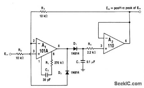
Discharge current through C1 minimized by using low-input-current voltage follower A2. R3 allows A1 to be clamped in OFF state by D2 to give faster recovery. Circuit operates much like ideal diode, but with C1 storing DC voltage equal to peak input voltage value. When input signal crosses zero, A1 drives D1 on and circuit output follows rising signal slope. When input signal reaches peak and reverses, C1 is left charged. Reverse diode connections to detect negative peaks. Value of R1 should be increased to 2.7 megohms if C1 is increased to 1μF to improve stability.-W. G. Jung, IC Op-Amp Cookbook, Howard W. Sams, Indianapolis, IN, 1974, p 196-197. (View)
View full Circuit Diagram | Comments | Reading(728)
SUBAUDIO_FREQUEIICY_METER
Published:2009/7/14 21:52:00 Author:Jessie

Provides meter indication of frequencies from 0.2 to 10 cps. Responds rapidly to changes in input frequency. Input signal is conyerted to square wave by limiting and differentiating network and bistable flip-lop, with period of square wave indicated on meter calibrated in pulses per minute. By alternately charging each one of pair of capacitors, steady voltage is maintained on capacitor connected to meter while other is charging.-Fast Acting Subaudio Frequency Meter, Electronic Circuit Design Handbook, Mactier Pub. Corp., N.Y., 1965, p 150. (View)
View full Circuit Diagram | Comments | Reading(859)
TEN_FREQUENCY_STANDARD
Published:2009/7/14 21:51:00 Author:Jessie

Stable crystal switching oscillator, isolation amplifier, multiplier, mixer, and audio amplifier give choice of ten fundamental frequencies, between 10 and 20 Mc, with harmonic output from 20 to 480 Mc, For zero-boating with unknown input frequency being measured.- Portable Frequency Standard Between 10 and 480 Mc, Electronics, 35:18, p 64. (View)
View full Circuit Diagram | Comments | Reading(687)
TEMPERATURE_COMPENSATED_CURRENT_SOURCE1
Published:2009/7/14 21:50:00 Author:Jessie
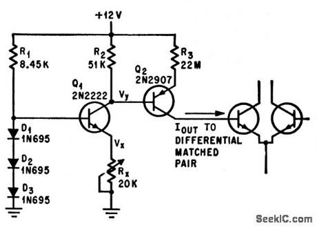
Presents 1,000 meg of output impedance while supplying up to 200 na of temperature-compensated current. Germanium diodes serve as compensating network drawing 1.3 ma. Based on fact that matched transistor pairs have base-current temperature coefficients that are predictable as function of operating current-C. C. Hanson, Low. Drift Current Generator Compensates for Temperature, Electronics, 39:12, p 108-109. (View)
View full Circuit Diagram | Comments | Reading(679)
SINGLE_IC_TOUCH_TONE_ENCODER
Published:2009/7/14 21:58:00 Author:Jessie

Uses ME8900 tone generator made by Microsystems International, Ottawa, Canada, to generate pairs of audio frequencies for telephone signaling. Standard Touch-Tone pad provides column and row switch closures for pins 4, 5, 6, and 8 going to low-frequency parallel-T oscillators of IC and for pins 9, 10, 11, and 12 of high-frequency oscillator-C. D. Rakes, Integrated Circuit Projects, Howard W. Sams, Indianapolis, IN, 1975, p 100-101. (View)
View full Circuit Diagram | Comments | Reading(1650)
VIDEO_NEGATIVE_VIEWER
Published:2009/7/14 21:58:00 Author:Jessie


This circuit will invert the video while maintaining sync polarity. Therefore, it will produce a negative image of the video signal. The sync is stripped by TR1, TR2, and IC1a and IC1b. Then it controls analog switches IC2a and IC2b to maintain sync polarity while switching in the inverted video produced by inverter TR3. TR4 is an emitter-follower for low output impedance. The unit was originally intended for viewing photographic negatives on a video monitor.
(View)
View full Circuit Diagram | Comments | Reading(1185)
0_TO_±10_V_PROGRAMMABLE_PEAK_DETECTOR
Published:2009/7/14 21:55:00 Author:Jessie

Principal components are Precision Monolithics CMP-11CJ voltage comparator, SMP81FY sample-and-hold amplifier, SN74LS136N open-collector EXCLUSIVE-OR gate package, and DG201 quad analog switch DC accuracy is within 5 mV at zero scale and within 10 mV at full scale. Resistors and diodes provide input overvoltage protection for comparator. Comparator continuously examines difference between analog input voltage and voltage peak held by sample-and-hold amplifier, If input exceeds held value, new input is held.-D. Soderquist, Polarity Programmable Peak Detector, Precision Monolithics, Santa Clara, CA, 1978,AN-27. (View)
View full Circuit Diagram | Comments | Reading(1562)
RING_DETECTOR
Published:2009/7/14 21:54:00 Author:Jessie

Optoisolator using neon lamp and light-dependent resistor serves as interface between telephone line and line-operated remote bell. Neon fires reliably from nominal 100-VAC ring signal, while capacitor C1 provides isolation required to prevent latch-up by sustaining voltages within range of phone-line quiet battery. If optional protective varistor RIC1 is added, rating of capacitor can be reduced to 400 V. Triac Q1 in series with primary of line transformer provides synchronization to 20-Hz ringing frequency of phone system.-W. D. Kraengel, Jr. Ring Detector Optically Interfaces Phone, EDN Magazine, Aug. 5.1978, p 80 and 82. (View)
View full Circuit Diagram | Comments | Reading(2121)
RGB_TO_NTSC_CONVERTER
Published:2009/7/14 21:54:00 Author:Jessie

This figure shows an RGB-to-NTSC converter circuit. Note that the input sweep rates, interlace, overscan, and program content must be TV-compatible if you want useful results. The AD722 is manufactured by Analog Devices. (View)
View full Circuit Diagram | Comments | Reading(4870)
LOGAMP_ZERO_CROSSING_DETECTOR
Published:2009/7/14 21:54:00 Author:Jessie


Feedback current for A1 creates logarithmic output voltage due to diodes D1 and D2. A1 is connected in feedforward mode to optimize speed and minimize phase error at high frequencies. 0utput voltage is nominally ±Vf, where Vf is forward voltage drop of either diode. Dynamic range of circuit is about 70 dB. If higher or constant output voltages are required, add optional connection of saturated switch that delivers 0-5 V output.-W. G. Jung, IC Op-Amp Cookbook, Howard W Sams, Indianapolis, IN, 1974, p229-230. (View)
View full Circuit Diagram | Comments | Reading(711)
PULSE_FREQUENCY_DIVIDER
Published:2009/7/14 21:40:00 Author:May

Plate-to-cathode coupled blocking oscillator is used to divide from high to low pulse frequency, as required in radar distance-mark generator. Circuit is highly stable with respect to heater voltage variations.-NBS, Handbook Preferred Circuits Navy Aeronautical Electronic Equipment, Vol. 1, Electron Tube Circuits, 1963, p N7-1. (View)
View full Circuit Diagram | Comments | Reading(699)
FSK_GENERATOR
Published:2009/7/14 22:10:00 Author:Jessie

Simple frequency-shift keyer uses Exar XR-2206C IC. Keying input is applied to pin 9. Mark frequency f1 is 1/R1C and space frequency f2 is 1/R2C, with C connected between pins 5 and 6.-E. Noll, VHF/UHF Single-Frequency Conversion, Ham Radio, April 1975, p 62-67. (View)
View full Circuit Diagram | Comments | Reading(1329)
VOLTAGE_LEVEL_LATCH
Published:2009/7/14 22:09:00 Author:Jessie

Circuit uses comparator to latch after input reaches predetermined threshold level. Output of IC1 then goes high and enables input of strobe Q2 to prevent output from going low. High level on reset input will turn off Q1, removing supply voltage from open collector output of IC1 and removing latch condition Comparator will operate on supplies ranging from single 5-V level to dual ±15V. – M. W Bair, IC Comparator Doubles as a Latch, EDN Magazine,April 20,1975,p 72. (View)
View full Circuit Diagram | Comments | Reading(1364)
MEASURING_1_CPS_F_M_DEVIATION
Published:2009/7/14 22:10:00 Author:Jessie
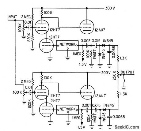
Foster-Seely discriminator uses RC elements in feed-back loops of amplifiers to simulate conventional LC tuned circuits. Upper cascode amplifier, cathode follower, and feedback loop resonate slightly above center frequency, while lower half of circuit resonates below center frequency. Circuit works well up to 500 kc.-H. D Crawford, F-M Discriminator Without Tuned Circuits, Electronics,36:48, p 36. (View)
View full Circuit Diagram | Comments | Reading(556)
PCM_FREQUENCY_REFERENCE
Published:2009/7/14 21:39:00 Author:May

Coherently switched oscillator, 90° phase shifter, Schmitt trigger, and frequency-dividing multivibrator and flip-flop together derive constant-frequency square-wave output clock signal from frequency-shifted subcarrier oscillator of f-m/f-m telemetry system.-R. C. Onstad, New Coherent Keyer Simplifies Pulse-Code Telemetry, Electronics, 35:26, p 71-73. (View)
View full Circuit Diagram | Comments | Reading(598)
ZERO_DETECTOR_WITH_HYSTERESIS
Published:2009/7/14 21:38:00 Author:May

ZERO DETECTOR WITH HYSTERESIS-Circuit using one section of Harris HA-4900/4905 precision quad comparator as Schmitt trigger has 100-mV hysteresis. Suitable for applications requiring fast transition times at output even though input signal approaches zero crossing slowly. Hysteresis loop also reduces false triggering by input noise. Output jumps to 4.2 V at instant when input reaches -100 mV after dropping to 0 V. Output drops from 4.2V to 0 V when input passes through 0 V in positive direction and reaches +100 mV.- Linear & Data Acquisition Products, Harris Semiconductor, Melbourne, FL, Vol. 1, 1977, p 2-96.
(View)
View full Circuit Diagram | Comments | Reading(1290)
CASCADED_DISTANCE_MARK_DIVIDER
Published:2009/7/14 21:38:00 Author:May

With 1-mile markers used as input trigger, output A, B, and C give 2 to 5,10 to 25, and 20 to 50-mile distance marks, respectively, Grid Potenliometers control exact mile mark obtained at each output,-NBS, Handbook Preferred Circuits Navy Aeronautical Electronic Equipment. Vol.1, Electron Tube Circuits,1963, p N7-5. (View)
View full Circuit Diagram | Comments | Reading(536)
| Pages:594/2234 At 20581582583584585586587588589590591592593594595596597598599600Under 20 |
Circuit Categories
power supply circuit
Amplifier Circuit
Basic Circuit
LED and Light Circuit
Sensor Circuit
Signal Processing
Electrical Equipment Circuit
Control Circuit
Remote Control Circuit
A/D-D/A Converter Circuit
Audio Circuit
Measuring and Test Circuit
Communication Circuit
Computer-Related Circuit
555 Circuit
Automotive Circuit
Repairing Circuit