Basic Circuit
BUFFERED_PEAK_DETECTOR
Published:2009/7/14 21:52:00 Author:Jessie | From:SeekIC

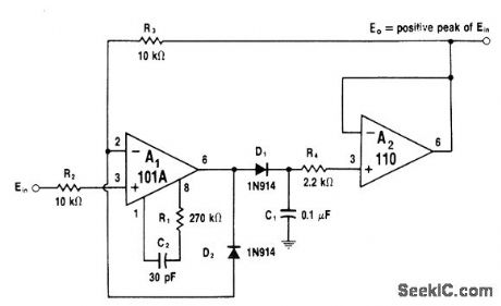
Discharge current through C1 minimized by using low-input-current voltage follower A2. R3 allows A1 to be clamped in OFF state by D2 to give faster recovery. Circuit operates much like ideal diode, but with C1 storing DC voltage equal to peak input voltage value. When input signal crosses zero, A1 drives D1 on and circuit output follows rising signal slope. When input signal reaches peak and reverses, C1 is left charged. Reverse diode connections to detect negative peaks. Value of R1 should be increased to 2.7 megohms if C1 is increased to 1μF to improve stability.-W. G. Jung, IC Op-Amp Cookbook, Howard W. Sams, Indianapolis, IN, 1974, p 196-197.
Reprinted Url Of This Article:
http://www.seekic.com/circuit_diagram/Basic_Circuit/BUFFERED_PEAK_DETECTOR.html
Print this Page | Comments | Reading(3)

Article Categories
power supply circuit
Amplifier Circuit
Basic Circuit
LED and Light Circuit
Sensor Circuit
Signal Processing
Electrical Equipment Circuit
Control Circuit
Remote Control Circuit
A/D-D/A Converter Circuit
Audio Circuit
Measuring and Test Circuit
Communication Circuit
Computer-Related Circuit
555 Circuit
Automotive Circuit
Repairing Circuit
Code: