
Circuit Diagram
Index 596
VIDEO_AMPLIFIER_WITH_SYNC_STRIPPER_AND_DC_RESTORER
Published:2009/7/14 22:11:00 Author:Jessie

This circuit transmits 220-MHz (-3-dB bandwidth) video signals while stripping off the sync pulse and performing dc restoration. It is configured for a typical video cable-driver application driving a double-terminated 75-Ω load. In other words, the HFA1103 (IC3) is configured for a gain of +2 to ensure unity gain overall. The HFA1103 video op amp is specially designed to perform sync stripping. Its open-emitter NPN output forms an emitter-follower with the load resistor, and passes the active video signal while virtually eliminating the negative sync pulse. Residual sync, defined as the remainder of the original -300-mV sync pulse, referenced to ground, is only 8 mV at the cable output of the HFA1103. Because the HFA1103 contains no active pull-down, output linearity degrades as the signal approaches 0 V. To deal with this, a 6.8-kΩ pull-up resistor (R8) and a 75-Ω pull-down resistor (R10) on the output ensure a fixed positive offset voltage, in this case, +50 rnV. This offset was arbitrarily chosen as a good compromise between linearity near the dc level and minimum residual sync. Increasing R8 decreases residual sync at the expense of linearity. Conversely, lowering R8, decreases linearity error, but increases residual sync. This circuit achieves dc restoration by using a CA5260 dual op amp (IC1a, IC1b) coupled with a sample-and-hold circuit, based on a 74HC4053 switch (IC2). Vin ,consisting of the input video signal and a dc offset (Vdc) ,is connected to the noninverting input of (View)
View full Circuit Diagram | Comments | Reading(1358)
TWO_PHASE_OSCILLATOR
Published:2009/7/14 22:11:00 Author:Jessie

Unknown signal to be analyzed is multiplied independently by each of two output reference signals, A and B. Oscillator uses two 90° phase-shift networks and 180° of phase shift in amplifier. Gain of 0.98 in cathode follower makes circuit accurate over 10:1 frequency range.-T. B. Fryer, Frequency Analyzer Uses Two Reference Signals, Electronics, 32:18, p 56-57. (View)
View full Circuit Diagram | Comments | Reading(857)
LEVEL_INDICATOR
Published:2009/7/14 22:10:00 Author:Jessie

Visual indication of voltage level is achieved with two TIL203 LEDs, three resistors, and any opamp that can provide 15-mA output current. If input voltage momentarily or permanently exceeds most positive reference level, LED1 is switched on. If voltage falls below negative or least positive reference level, LED1 goes off and LED2 comes on. Article gives design equations for determining values of R1 and R2. For levels of +2 V to turn LED1 on and -1.2 V to turn LED2 on, both R1 and R2 are 10K.-E. J. Richter, Op Amp Makes Visual Level Indicator, EDN Magazine, May 5, 1974, p 73. (View)
View full Circuit Diagram | Comments | Reading(1019)
600_Hz_CLAMP
Published:2009/7/14 22:29:00 Author:Jessie

Polar clamp was developed to provide overvoltage input protection for ±6 VDC teleprinter signals at 10mA. Circuit will withstand input transients up to 120 VDC at 20mA. When input exceeds emitter-base break-down voltage of Q1, Q2 becomes forward-biased for clamping of input. With excessive negative input, Q1 is forward-biased and emitter-base path in Q2 completes clamping action.-R. R. Breazzano, A Polar Clamp, EDN|EEE Magazine, June 15, 1971, p 59. (View)
View full Circuit Diagram | Comments | Reading(833)
TAPE_AS_RTTY_BUFFER
Published:2009/7/14 22:27:00 Author:Jessie

Developed to give constant-speed amateur radioteletype transmissions despite erratic keyboarding speeds Uses NE555 timer chip as free-running MVBR whose speed can be varied by R1 down to about 1 character every 15 s or up to full machine speed. Can be used with any automatic send-receive machine. Keep enough slack in punched paper tape to permit backspacing and correcting errors before they are sent. With 5-V supply shown, 6-V SPST DC relay can be used.-B. Gulledge, Mechanical RITY Buffer, 73 Magazine.Oct.1976, p 74. (View)
View full Circuit Diagram | Comments | Reading(688)
6_V_PHONO_AMPLIFIER
Published:2009/7/14 22:26:00 Author:Jessie
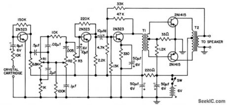
Provides 300 mw at 10% distortion. Bass control R1 and treble control R2 are 50K linear taper. Volume control R3 is 10K audio taper.- Transistor Manual, seventh Edition, General Electric Co.,1964,p 376. (View)
View full Circuit Diagram | Comments | Reading(745)
FOLDBACK_CURRENT_LIMITER
Published:2009/7/14 22:26:00 Author:Jessie

Provides overload and short-circuit protection for load while isolating malfunctioning circuit from other loads on common supply bus. In normal operation, Q1 is saturated. When load attempts to draw more than this saturation value, base current of Q1 cannot maintain saturation so voltage across unmarked resistor drops and current through Q1 drops correspondingly. When load is shorted, Q2 goes off and short-circuit current folds back to safe lower value. Choose value of unmarked resistor to ensure saturation of Q1 at load current. -S. T. Venkataramanan, Simple Circuit Isolates Defective Loads, EDN Magazine, Jan. 20, 1978, p 114. (View)
View full Circuit Diagram | Comments | Reading(4655)
VIDEO_DISTRIBUTION_AMPLIFIER
Published:2009/7/14 22:26:00 Author:Jessie
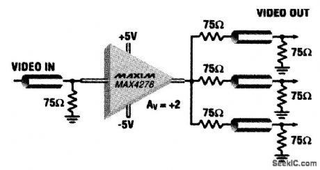
This video distribution amplifier uses a single MAX4278 with a gain of 2 (6 dB) so that three 75-Ω loads can be driven from one 75-Ω source. Each driven load has a source impedance of 75Ω. Gain is flat to 0.1 dB up to 150 MHz. (View)
View full Circuit Diagram | Comments | Reading(4279)
CRYSTAL_LAPPING_CONTROL
Published:2009/7/14 22:25:00 Author:Jessie

Noise signal generated by crystals being lapped is amp lified by receiver. Noise peak, which occurs whom crystal thickness produces frequency to which receiver is tuned, triggers circuit that automatically shuts down lapping machine. Useful for crystals up to 14 Mc.-J. F.Brumach, R. E. Bennett, and R.P. Chalker, Trigger Circuit Controls Quartz Crystal Lapping, Electronics, 31;29, p 66-67, (View)
View full Circuit Diagram | Comments | Reading(652)
FREQUENCY_MONITOR_CONTROLS_DEPOSITION_OF_THIN_FILMS
Published:2009/7/14 22:24:00 Author:Jessie
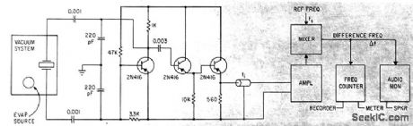
Film is deposited on quartz crystal mounted alongside substrate in vacuum, causing crystal frequency to change. Amplified output of Colpitts crystal oscillator is fed through coax to mixer that also receives reference frequency, and beat-frequency difference (related to film thickness) is indicated on counter.-S. J. Lins and P.E. Oberg, Avtomatic Deposition Control, Electronics, 36:13,P 33-35. (View)
View full Circuit Diagram | Comments | Reading(772)
PREFERRED_POWER_AMPLIFIER
Published:2009/7/14 22:23:00 Author:Jessie
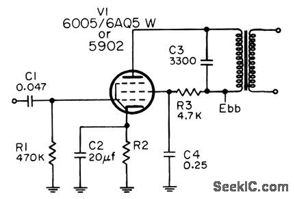
For 6AQ5W, with plate supply of 250 v, output is 115 v to transformer at 2.21 w for 6 v rms input. For 5902, with plate supply of 150 v, output to transformer is 75 v at 0.8 w for 5 v rms input.-NBS, Handbook Preferred Circuits Navy Aeronautical Electronic Equipment, Vol. I, Electron Tube Circuits, 1963, PC 61, p 61-2. (View)
View full Circuit Diagram | Comments | Reading(1626)
WEAK_SIGNAL_CAPTURE
Published:2009/7/14 22:32:00 Author:Jessie
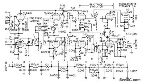
High-Q trap in reactance-tube circuit attenuates stronger of two signals, to permit capture of weaker of two cochannel f-m signals, as often required in police, military, and telemetering systems, Trap introduces depression in frequency re sponse of third i-f stage, centered on frequency of stronger signal.-E. J, Baghdady and G. J. Rubissow, Dynamic Trap Captures Weak F-M Signals, Electronics, 32:2, p 64-66. (View)
View full Circuit Diagram | Comments | Reading(1022)
LONG_DELAYS
Published:2009/7/14 22:31:00 Author:Jessie

Delays up to 2 hours are obtained, using unijunctiom transistor Q1 as trigger for scr and Q2 as free-running oscillator. Only 2 na through timing resistor R1 will provide triggering.-D. V. Jones, Quick-On-The-Trigger Design, Electronics, 38:12, p 105-110. (View)
View full Circuit Diagram | Comments | Reading(850)
AUDIBLE_LINE_MONITOR
Published:2009/7/14 22:31:00 Author:Jessie


Audio oscillator coupled to simple relay circuit gives alerting tone when power fails even momentarily. C2 determines duration of tone. With 2900 μF, tone lasts about 1 s, as warning that clocks will need resetting, Q2 is any PNP audio power transistor, K1 is 115-V SPDT relay, and PL1 is neon lamp.-J. R. Nelson, Some Ideas for Monitoring A.C. Power Lines, CQ, July 1973, p 56. (View)
View full Circuit Diagram | Comments | Reading(932)
150_MHZ_VIDEO_LINE_DRIVER
Published:2009/7/14 22:31:00 Author:Jessie

This line driven uses an Analog Devices P/N AD9631/9632 and has a bandwidth of better than 150 MHz (View)
View full Circuit Diagram | Comments | Reading(645)
5_V_PEAKS_UPTO_2_MHz
Published:2009/7/14 22:31:00 Author:Jessie

Peak-to-peak detector using Optical Electronics 9412 opamps gives DC output voltage equal to peak-to-peak amplitude of sine-wave input voltage Opamp charges memory capacitor Cm during negative half of input cycle and performs DC clamp(restoration) on positive half. Circuit has high input impedance With 0.1-μF memory capacitor, 10-V pulse is acquired in 10μS,For 5-V sine-wave input, maximum frequency is 0.8 MHz, but 0.01-μF memory capacitor boosts frequency capability to 2 MHz, - A Wideband Peak-to-Peak Detector, Optical Electronics, Tucson, AZ、Application Tip 10176. (View)
View full Circuit Diagram | Comments | Reading(1237)
ZERO_POINT_WITH_OVERVOLTAGE_PROTECTION
Published:2009/7/14 21:37:00 Author:May

Used to protect voltage-sensitive load from excessive line voltage Switch section operates conventionally to turn on triac almost immediately after each zero crossing between half-cycles,For normal line voltages, SCR Q3 is off. When overvoltage condition is sensed during any half-cycle, SCR Q1 s turned on, discharging C2 and turning Q2 off. This allows Q3 to turn on and divert triac gate drive, removing power from load As long as overvoltage condition exists, Q1 is turned on each half-cycle and C2 is unable to charge enough to turn Q2 on,When overvoltage condition ceases, C2 charges to voltage set by D8 in about 20 ms, saturatingQ2 so Q3 turns off and Q4 turns on R2 can be set to allow line voltage variations from almost 0 to 11 v.-“Circuit Applications for the Triac,” Motorola, Phoenix, AZ, 1971, AN-466, p 14. (View)
View full Circuit Diagram | Comments | Reading(1898)
PREFERRED_VOLTAGE_AMPLIFIER
Published:2009/7/14 22:31:00 Author:Jessie

Amplifies 10 to 70-my signals to level needed to driveaudio power amplifier. For 5751, amplification is 335 , maximum output is 23 v rms,and 3-db response is 10 cps to 20 kc. For 6112, maximum output is 26 v rms,amplification is 370, and 3-db bandwidth is 10 cps to 30 kc.-NBS, Handbook Preferred Circuits Navy Aeronautical Electronic Equipment, Vol. I, Electron Tube Circuits, 1963, PC 60, p 60-2. (View)
View full Circuit Diagram | Comments | Reading(1272)
MEASURING_NEARLY_SIMULTANEOUS_EVENTS
Published:2009/7/14 22:30:00 Author:Jessie

Used for measuring 12 events that can be as close together 20 nsec and as far apart as 200 nsec. Twelve identical circuits, one for each trigger, drive magnetostrictive delay line for serializing events.-R. P. Rufre, How to Measure Simultaneous Events with Magnetostrictive Delay Lines, EEE, 14:5, p44-49. (View)
View full Circuit Diagram | Comments | Reading(776)
VCO_FOR_FREQUENCY_SYNTHESIZER
Published:2009/7/14 21:37:00 Author:May

Digital synthesizer uses two vco's to covel 190 to 400 Mc, giving choice of 3,500 channels for transceiver in military uhf band without tuning. Output to prescaler is limited with hotcarrier diodes. Control voltage acts on diffused-junction varactors.-L. F. Blachowicz, Dial any Channel,500 Mhz,Electronics,39:9,p 60-69. (View)
View full Circuit Diagram | Comments | Reading(989)
| Pages:596/2234 At 20581582583584585586587588589590591592593594595596597598599600Under 20 |
Circuit Categories
power supply circuit
Amplifier Circuit
Basic Circuit
LED and Light Circuit
Sensor Circuit
Signal Processing
Electrical Equipment Circuit
Control Circuit
Remote Control Circuit
A/D-D/A Converter Circuit
Audio Circuit
Measuring and Test Circuit
Communication Circuit
Computer-Related Circuit
555 Circuit
Automotive Circuit
Repairing Circuit