
Circuit Diagram
Index 587
Inductive electronic doorbell 2
Published:2011/8/7 22:56:00 Author:Ecco | Keyword: Inductive electronic doorbell

The inductive electronic doorbell circuit is composed of the infrared transmitter, infrared receiver circuit and music generating circuit, ans it is shown in Figure 3-116. Infrared transmitter circuit consists of the time-base integrated circuit lCI, infrared light-emitting diode VL, resistors Rl, R2, capacitors Cl, C2 and potentiometer RP. Infrared receiver circuit consists of the infrared photodiode VDl, resistors R3-R5, capacitors C3-C5 , inductor L and infrared receiving and dealing the integrated circuit IC2. Music generating circuit is composed of the music IC IC3, resistors R6, R7, diode VD2, capacitor C7, transistor V, and the speaker BL.
(View)
View full Circuit Diagram | Comments | Reading(1845)
Inductive electronic doorbell 3
Published:2011/8/7 23:05:00 Author:Ecco | Keyword: Inductive electronic doorbell

The inductive electronic doorbell circuit is composed of the trigger control circuit and audio output circuit, and it is shown in Figure 3-117. Trigger control circuit consists of pyroelectric infrared detection module lCl, doorbell circuit IC2, resistors Rl-R4 and capacitors Cl, C2. Audio output circuit consists of transistors Vl, V2, resistor R5 and speaker BL. Rl-R5 use the metal film resistors or carbon film resistors. Cl and C2 select the aluminum electrolytic capacitors with the voltage value being greater than 6V. Vl uses the S9013 or 3DG6 NPN transistor; V2 uses the C8550 or S8550 silicon PNP transistor.
(View)
View full Circuit Diagram | Comments | Reading(1148)
Password electronic doorbell 1
Published:2011/8/8 1:52:00 Author:Ecco | Keyword: Password electronic doorbell

The password electronic doorbell circuit is composed of the electronic password circuit and music occurred circuit, and it is shown in Figure 3-118. Electronic password circuit consists of integrated circuits lCl and keys Sl-S6, diodes VDl-VD5. lCl is the electronic password IC, its pin 1-3 and pin 6 are the effective transmission input ends, and pin 7 is the reset end, when the pin 1, 2, 3, 6 are input high trigger level in turn, only pin 5 outputs high. Otherwise, pin 5 is in low level. R uses the 1/4W carbon or metal film resistor. VDl-VD5 select the 1N4148 silicon switch diodes.
(View)
View full Circuit Diagram | Comments | Reading(1779)
Password electronic doorbell 2
Published:2011/8/8 1:58:00 Author:Ecco | Keyword: Password electronic doorbell

The password electronic doorbell circuit is composed of the trigger circuit and music generating circuit, and it is shown in Figure 3-119. Trigger circuit is composed of the buttons S1-S9, four NAND gate Schmitt trigger integrated circuit IC1 and the external RC components. Music generating circuit is composed of the integrated circuits lC2 and 1C3, transistors Vl and V2, diodes VDl-VD3, speaker BL and the RC components. Rl-R9 select the V4W carbon film resistors. CI-C5 select the aluminum electrolytic capacitors with voltage in lOV. VDl-VD4 select the 1N4148 silicon switch diodes. Vl uses S9013 silicon NPN transistor; V2 uses Sg012 silicon PNP transistor.
(View)
View full Circuit Diagram | Comments | Reading(1590)
Typical application circuit of 5G168 holiday lights control IC
Published:2011/8/7 21:16:00 Author:Ecco | Keyword: Typical application, holiday lights , control IC
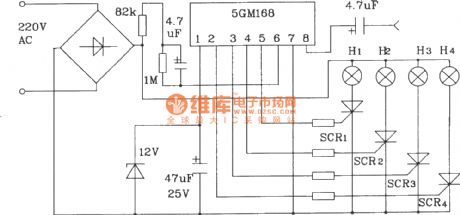
In the circuit, pin 9, 10 are floating to drive four ways of lights for Love-style jump. Changing external R, C size of pin 6 can change the frequency of flashing lights. If the pin 8 is input audio signal, the lights' cycle will change with the audio AC signal.
(View)
View full Circuit Diagram | Comments | Reading(597)
Flashing electronic doorbell
Published:2011/8/7 22:37:00 Author:Ecco | Keyword: Flashing electronic doorbell

The flashing electronic doorbell circuit is composed of the power supply circuit, audio input trigger circuit, multivibrator, and it is shown in Figure 3-124. The power supply circuit consists of the step-down capacitor C6, resistor RlO, rectifier diode VD3, regulator C5. Audio input trigger circuit s composed of the audio sensor trigger circuit B, transistors Vl, V2, diode VDlR4 and capacitors Cl, C2. Multivibrator is composed of the time-base integrated circuit IC, resistors R5, R6 and capacitors C3, C4. Flash circuit consists of resistors R7-R9, rectifier diode VD4, capacitors C7, C8, thyristor VT and flash components.
(View)
View full Circuit Diagram | Comments | Reading(1006)
Ding-dong electronic doorbell
Published:2011/8/7 21:09:00 Author:Ecco | Keyword: Ding-dong electronic doorbell

The ding-dong electronic doorbell circuit is composed of the power supply circuit, trigger control circuit, audio oscillator output circuit, and it is shown in Figure 3-125. Power supply circuit is composed of the power transformer T, rectifier diodes VDl-VD4 and filter capacitor Cl. Trigger control circuit is composed of the doorbell button, control circuit S, diode VD5, capacitor C2 and resistors Rl, R2. Audio oscillator A consists of the Dl, D2 which are inside of four NAND gate IC (Dl-D4) and resistor R3, capacitor C3. Audio oscillator B consists of the D3, D4 which are inside of IC and potentiometer RP, capacitor C4. Audio output circuit consists of resistors R4, R5, diodes VD6, VD7, transistor V, and the speaker BL.
(View)
View full Circuit Diagram | Comments | Reading(3610)
Politely welcoming electronic doorbell
Published:2011/8/7 21:38:00 Author:Ecco | Keyword: Politely welcoming, electronic doorbell

The politely welcoming electronic doorbell circuit is composed of the trigger control circuit, audio amplifier output circuit, music circuit, voice delay control circuit, and it is shown in Figure 3-122. Trigger control circuit is composed of the doorbell button S, magnetic switches SA, transistors V4, V5, resistors R3, R4, R6, diodes VD2, VD3, and capacitors Cl, C2. Audio amplifier output circuit consists of transistor V3 and speaker BL. The music circuit consists of music integrated circuit ICl and resistor Rl. Voice circuit is composed of the voice IC lC2 and resistor R5, capacitors C4, C5.
(View)
View full Circuit Diagram | Comments | Reading(1916)
Recordable electronic doorbell
Published:2011/8/7 21:43:00 Author:Ecco | Keyword: Recordable electronic doorbell

The recordable electronic doorbell is composed of the recording and playback integrated circuit IC, resistors Rl-R6, capacitors Cl-C4, microphone BM, speaker BL, control buttons Sl, S2, battery GB and LED VL, and it is shown in Figure 3-123. Rl-RS select 1/4W metal film resistors or carbon film resistors; R6 select the lW metal film resistor. Cl-C4 select monolithic capacitors. VL chooses the φ3mm green light-emitting diode. IC uses the SR9GlOA or ISDll10 audio recording and playback IC. S1 select the miniature moving together button; S2 uses the bell button. BL uses the 0.25W, 8Ω dynamic speaker.
(View)
View full Circuit Diagram | Comments | Reading(2889)
Low-frequency FM generator circuit composed of two NE566V ICs
Published:2011/8/8 8:02:00 Author:nelly | Keyword: Low-frequency, FM, generator
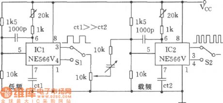
As shown in the picture, two NE566V ICs form the low-frequency FM generator. In the picture, ICl NE566V is used to produce the signal, and IC2 works on the carrier signal. Ctl can be selected to determine the modulation frequency range. The Ct2 can be selected to determine the core frequency. The output modulation can use the Sl to choose the square wave and triangular wave, thus the square wave modulation and triangular wave modulation can be achieved. (View)
View full Circuit Diagram | Comments | Reading(942)
The improvement of 555 Great Wall floor fan electronic selection time circuit
Published:2011/8/4 9:00:00 Author:nelly | Keyword: Great Wall, floor fan, selection time

The great wall FS7-40 floor fan adopts the general mechanical electromagnetic relay,as a result,when we are shifting,it's always being the mechanical metal contact's contacting and opening which produces the mechanical noise and discharge spark. Using solid relay and connecting control circuit which consists of 555 can solve this problem. The figure 12-16 is an improved selection time circuit.The solid relay adopts sp1110-2.Its input voltage is between 2vand 6v,and the input current is between 10mAand 50mA,the on state current is 3A. To avoid the influence of the power voltage's change on the triggering and turn-on,we should use w7805 or w7806 to stabilize the +12V original power voltage. Through changing the vibration period and the Duty ratio can Change the RP1 and RP2. The R3 is the relay's limiting current.The D3 is used for the relay's over voltage protection.The R4 and C2 is used for absorpting the surge current to increase the safety.
(View)
View full Circuit Diagram | Comments | Reading(1467)
555 tri-state acousto-optic logic pen circuit
Published:2011/8/4 8:57:00 Author:nelly | Keyword: tri-state, acousto-optic, logic pen
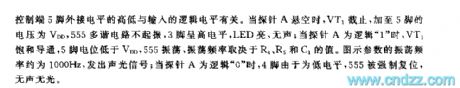
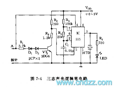
In fact, the 555's control site 5 foot and threshold site 6 foot are the input terminal of the voltage comparator I. If the 6 foot voltage is 5mv larger than the 5 foot's, the 555 will relability trig. Adding the DC voltage to the +/- shown on the figure 7-11. If the voltage is high, the LED1 lights. but if the voltage is low, the LED2 lights. Changing the rangeand RP1. When the two LED lights in turns, the measured voltage equals to multiply the range by the RP1. The measuring range has four planetary: 0-1v,0-10v,0-100v,0-1000v.
(View)
View full Circuit Diagram | Comments | Reading(1441)
The basic application circuit diagram of LT108X adjustable voltage regulator
Published:2011/8/7 6:27:00 Author:nelly | Keyword: adjustable voltage regulator

View full Circuit Diagram | Comments | Reading(854)
Basic constant current circuit diagram
Published:2011/8/7 6:27:00 Author:nelly | Keyword: constant current

View full Circuit Diagram | Comments | Reading(804)
The compare circuit diagram of LM324
Published:2011/8/7 8:36:00 Author:nelly | Keyword: compare

If you do not want to so much trouble, you can define the value of R2 at first. R1 uses the adjustable resistor to adjust the value of R1. At the point of V1, the multimeter is used to measure the voltage. When the voltage of V1 reaches the wanted threshold, the value of R1 will be defined. The threshold of the other voltage has the same principle.
(View)
View full Circuit Diagram | Comments | Reading(4169)
Mazda 95TAURUS (no power windows) gate lock circuit
Published:2011/8/4 8:56:00 Author:nelly | Keyword: power windows, gate lock

View full Circuit Diagram | Comments | Reading(686)
Positive dual periphery or driver circuit
Published:2011/7/27 2:10:00 Author:Fiona | Keyword: Positive dual periphery or driver circuit
SN55453/75453B is a externaldrive with or logic and it’s input is compatible with TTL or DTL circuit. SN55453/75453B’s input current is 300mA,with high inputvoltageand high conversion speed. The typicalapplication circuitis shown as above.
(View)
View full Circuit Diagram | Comments | Reading(548)
TDA9302H pin function in color TV and data circuit
Published:2011/7/28 8:29:00 Author:Fiona | Keyword: pin function, color TV, data circuit
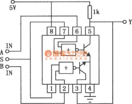
TDA9302H field scanning output integrated circuit
TDA9302H is a kind of new field scanning output intergrated circuit produced by Philips in the Netherlands.And it is widely used on Philips' new big-screen color TV .
1.Features
TDA9302H integrated circuit includes field excitation signal amplification circuit, field scanning output power amplifier circuit,field blanking pulse signal generating circuit, field scanning pump power supply circuit, and other auxiliary functions circuits.
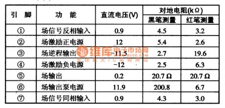
2. Pin function and data
TDA9302H integrated circuit uses 7-pin single in-line package, its pin function and data are listed in Table 71. Application data table is measured in Philips 29PT4423 big-screen TV.
(View)
View full Circuit Diagram | Comments | Reading(1139)
Current expansion circuit composed of μA741
Published:2011/8/4 21:25:00 Author:Rebekka | Keyword: Current expansion


Usually the output current of the op amp is about 10 ~ 30mA. For the operation amplifier circuit is composed of the μA741, When the output current is greater than 10 ~ 35mA, its output voltage will appear limiting phenomenon, that means the output voltage will be a greater distortion. When you need a higher output current, you can use the geminate transistor formed by the 2SC503 and 2SA503. The so-called geminate transistor means that its input and output characteristics are almost identical to the transistor. When you use it, it should be strictly selected. It can not be used randomly assigned. The circuit output current can be up to 120mA, the magnification times of the voltage is show as above.
μA741 Electrical Characteristics table (VD = ± 15V; TA = 25 ℃). (View)
View full Circuit Diagram | Comments | Reading(1163)
Over-temperature monitoring automatic control circuit diagram
Published:2011/8/4 21:54:00 Author:Rebekka | Keyword: Over-temperature monitoring , automatic control

The circuit is composed of a NAND gate circuit, a thermistor composition measurement, control circuit and sirens generating circuit. It uses a relay as the implementation circuit. Its structure is simple and easy to make, economical and practical. The constitution of the circuit is shown as above. (View)
View full Circuit Diagram | Comments | Reading(1220)
| Pages:587/2234 At 20581582583584585586587588589590591592593594595596597598599600Under 20 |
Circuit Categories
power supply circuit
Amplifier Circuit
Basic Circuit
LED and Light Circuit
Sensor Circuit
Signal Processing
Electrical Equipment Circuit
Control Circuit
Remote Control Circuit
A/D-D/A Converter Circuit
Audio Circuit
Measuring and Test Circuit
Communication Circuit
Computer-Related Circuit
555 Circuit
Automotive Circuit
Repairing Circuit