
Circuit Diagram
Index 588
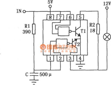
Timer circuit using the monostabillity free-send device
Published:2011/7/20 6:22:00 Author:Fiona | Keyword: the monostabillity free-send device, Timer

This circuit's characteristic is that input end has anti-interference protection measures to prevent malfunction caused by interference signals.In addition,the time process ends before the switch S is off,it increases reliability.
(View)
View full Circuit Diagram | Comments | Reading(884)
Electronic refrigerator temperature controller circuit diagram
Published:2011/8/4 21:53:00 Author:Rebekka | Keyword: temperature controller, Electronic refrigerator

Since the point A of this circuit sensor VD2 negative end potential design is 1 0 ℃, and V head is 0 V and it shows 00.0 , so the circuit uses3kΩ RP3. The pin 30 of theintegrated circuit 7170 is connected to the ground (shown in play x place). It makes the potential Vin of the head increase 1V. When commissioning VD2 sensor is in the ice water mixture, the potentiometer RP3 makes the head show 00.0 . Put the VD2 in boiling water, and the RP4 potentiometer makes the head show 100.0 , the debugging is brought to an end. (View)
View full Circuit Diagram | Comments | Reading(1715)
The Pin Function of TDA9302H on color image reveals and data circuit
Published:2011/7/27 1:58:00 Author:Fiona | Keyword: Pin Function, color image reveals, data circuit
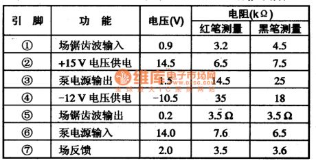
TDA9302H integrated circuit is also widely used on various color monitors .Table 72 shows the measured data that when TDA9302H is applied in Tsinghua Tongfang 5E multi-frequencycolor monitor.
(View)
View full Circuit Diagram | Comments | Reading(594)
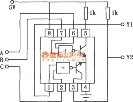
SN55452B/75452B positive dual periphery and Non-driver circuit
Published:2011/7/26 21:11:00 Author:Fiona | Keyword: positive dual periphery, non-driver circuit
SN55451B/75451B is a externaldrive with NAND logic and it’s input is compatible with TTL or DTL circuit. SN55451B/75451B’s input current is 300mA,with high inputvoltageand high conversion speed. The typicalapplication circuitis shown as above.
(View)
View full Circuit Diagram | Comments | Reading(513)
SN55451B/75451B positive dual periphery and driver circuit
Published:2011/7/26 20:55:00 Author:Fiona | Keyword: positive dual periphery, driver circuit
SN55451B/75451B is a externaldrive with and logic and it’s input is compatible with TTL or DTL circuit. SN55451B/75451B’s input current is 300mA.And it has high inputvoltageand high conversion speed. The typicalapplication circuitis shown as above.
(View)
View full Circuit Diagram | Comments | Reading(741)
Electric blanket temperature controller circuit composed of Y982 module
Published:2011/8/4 21:49:00 Author:Rebekka | Keyword: Electric blanket, temperature controller

Y982 power adjustment module can be used for a variety of electric heater control. It can be used for the adjustment of the size of used appliances power. It has a timer function. It is an ideal transfer function devices. Electric blanket temperature controller circuit composed of Y982 module is shown as above. (View)
View full Circuit Diagram | Comments | Reading(2969)
Ordinary low-noise broadband amplifier circuit diagram
Published:2011/8/2 2:40:00 Author:Rebekka | Keyword: Ordinary low-noise, broadband amplifier

The gain bandwidth of some integrated amplifier is small (about l ~ 2 MHz), the input noise is high and the conversion rate is low pressure (about 0.5 V/u s). The reason why the gain bandwidth is small is that the operational amplifier internal input class level shift from the transistor phase shift. Conversion rate is low, because the input stage emitter current is too small. Figure (a) shows the low noise amplifier broadband circuit composed of the application ordinary op-amp integrated chips OPA101. The circuit can increase the convert rate to 30 times, and its gain bandwidth can be close to l00MHz.
(View)
View full Circuit Diagram | Comments | Reading(837)
Frequency type electronic coded lock (LM567) circuit
Published:2011/7/20 20:39:00 Author:Fiona | Keyword: Frequency type, electronic coded lock

View full Circuit Diagram | Comments | Reading(2631)
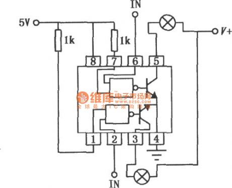
SN55454B/75454B positive dual periphery or non-driver circuit
Published:2011/7/30 6:56:00 Author:Fiona | Keyword: positive dual periphery , non-driver circuit
SN55454B/75454B is a externaldrive with NOR logic and it’s input is compatible with TTL or DTL circuit. SN55454B/75454B’s input current is 300mA,with high inputvoltageand high conversion speed. The circuit which is used as a multi-functional logic signal comparator to is shown as above.
(View)
View full Circuit Diagram | Comments | Reading(676)
Touch switch (CD4069) circuit composed of gate circuit
Published:2011/7/20 20:53:00 Author:Fiona | Keyword: Touch switch, gate circuit

View full Circuit Diagram | Comments | Reading(824)
Temperature-frequency conversion temperature controller circuit composed of NE555 and LM567
Published:2011/8/4 21:26:00 Author:Rebekka | Keyword: Temperature- frequency conversion, temperature controller

View full Circuit Diagram | Comments | Reading(2394)
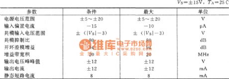
F1590 single supply with AGC wideband single op amp circuit diagram
Published:2011/8/4 21:21:00 Author:Rebekka | Keyword: Single Supply, AGC wideband , single op amp

F1590 and the United States Motorola MC1590 are similar and they have the same parameters. It uses double-ended input, double-ended output and AGC end. It also has the features of a high gain, frequency bandwidth, automatic gain control etc. - Iffi airborne radar communication, navigation receivers, video amplification, electronically controlled attenuator, mixer and so on. The typical application circuit is shown as above. (View)
View full Circuit Diagram | Comments | Reading(1751)
Light touching light control delay energy-saving switch circuit
Published:2011/7/20 21:26:00 Author:Fiona | Keyword: Light touching, light control, delay, energy-saving

View full Circuit Diagram | Comments | Reading(769)
Touching voice control lamp switch circuit
Published:2011/7/20 23:01:00 Author:Fiona | Keyword: Touching, voice control, lamp switch

View full Circuit Diagram | Comments | Reading(1356)
Nokia 8210 mobile phone travel charger circuit diagram
Published:2011/8/4 21:20:00 Author:Rebekka | Keyword: travel charger, Nokia mobile phone

The Nokia 8210 mobile phone travel charger produced by Shanghai has been marked on the shell: input AC220V/50Hz(≤30mA),output 4.2V(≤200mA). When people use it to charge the 3.6V rechargeable lithium battery, the red light will be turned off and green light turned on when the it is charged to 3.98V. the whole charging time is about 4 hours. The op amp in the circuit is used as the comparator.
(View)
View full Circuit Diagram | Comments | Reading(5481)
Op amp output short circuit protection method circuit diagram
Published:2011/8/4 21:01:00 Author:Rebekka | Keyword: Op amp, output short circuit, protection method

The protection method of the op amp's output short circuit is simple. It only needs to connect a small resistor R in series at the op amp output, the output short-circuit failure can be avoided. It is shown as above. If the resistor is connected to the internal feedback loop, it will have no influence on any performance but the voltage will decrease obviously(When the load is 2kΩ, the value is shown in the figure, Vo can be decreased by 10%). Another advantage of this circuit is: The circuit is also very stable for the external capacitive load. Even if the integrated operational amplifier has been added within the current limiting resistor, a small resistor should also be added at the external op amp output end. (View)
View full Circuit Diagram | Comments | Reading(2721)
Reflection loss bridge type circuit used to measure impedance matching
Published:2011/8/7 4:58:00 Author:Sophia | Keyword: Reflection loss bridge type circuit, measure impedance matching

In the high-frequency circuits, impedance matching is the key. If the problems of impedance mismatch and signal reflection appear, which will produce a standing wave to cause the abnormal condition of the signal transmission .
For example, in a 50Ω transmission line, if you connect a 50Ω load impedance, then all power is supplied to the load. Of course, it is the normal state when reflection power is 0.
When mismatch state is showed, the reflection coefficient, standing wave ratio (VSWR: Volt-age Standing Wave Ratio) and mismatch losses (ie reflection loss) and other terms can be used. (View)
View full Circuit Diagram | Comments | Reading(1121)
The bridge type T circuit of reducing the components of Notch filter
Published:2011/8/7 4:15:00 Author:Sophia | Keyword: The bridge type T circuit, reducing the components of Notch filter

The double-T circuit with less number of components achieves the notch filter circuitry, as well known as the T-bridge circuit, its application is few . Figure 1 is a typical example. In the circuit, the arrangement of substitute resistors and capacitors is neglected because of imbalanced value of capacitance. In this circuit, the ratio of resistors R1 and R2 make zero frequency with the largest attenuation changed. When R1 = R2 = 16kΩ, C = 0.01μF, fo = 11kHz, a large amount of attenuation is available. But when it is used, the condition is R1> R2, which is not very simple. (View)
View full Circuit Diagram | Comments | Reading(1788)
Non-inverting type ideal diode circuit formed by the OP amplifier
Published:2011/8/7 3:32:00 Author:Sophia | Keyword: Non-inverting type, ideal diode circuit, OP amplifier
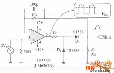
Rectifier power supply circuit is indispensable one of the power supply circuits, even if except the power supply circuit, it is also often used in measuring how the current (AC) signal is converted into direct current (DC). But when high-precision AC to DC conversion is carried out, there is a problem caused by the diode forward voltage VF, that the temperature coefficient of the insensitive zone and VF is about-2mV / ℃. Therefore, the high-precision AC to DC conversion is necessary, OP amplifier would be a common element, meanwhile the diode is inserted in the feedback loop, which is ideal diode circuit. (View)
View full Circuit Diagram | Comments | Reading(1206)
The full-wave rectification circuit with the absolute value of the idealized diode
Published:2011/8/7 2:46:00 Author:Sophia | Keyword: The full-wave rectification circuit, idealized diode, absolute value
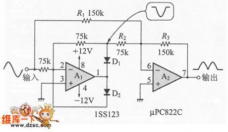
Figure 1 is the absolute value circuit of the amplifier OP often mentioned on a good textbook, that is full-wave rectifier circuit. Circuit is constituted of half-wave rectifier circuit A1 and the addition circuit A2(for the subtraction operation when the sign is oppositive ) with OP amplifiers ideal diode.In this circuit when the input is positive half cycle, diode D1 turns on, the circuit will output the negative half-wave rectified wave. This signal adds input signal (R2 = 0.5R1 is necessary), which get a positive output.
When the input is negative, diode D2 is not conducting, and inverting amplifier composed of the resistance R1, R3 begans to move.
(View)
View full Circuit Diagram | Comments | Reading(2113)
| Pages:588/2234 At 20581582583584585586587588589590591592593594595596597598599600Under 20 |
Circuit Categories
power supply circuit
Amplifier Circuit
Basic Circuit
LED and Light Circuit
Sensor Circuit
Signal Processing
Electrical Equipment Circuit
Control Circuit
Remote Control Circuit
A/D-D/A Converter Circuit
Audio Circuit
Measuring and Test Circuit
Communication Circuit
Computer-Related Circuit
555 Circuit
Automotive Circuit
Repairing Circuit