
Circuit Diagram
Index 591
Electric water heater temperature controller
Published:2011/8/5 2:08:00 Author:Ecco | Keyword: Electric water heater , temperature controller
The electric water heater temperature controller circuit is composed of the power supply circuit, leakage protection circuit, temperature control circuit, water level indication and anti-dry circuit, and it is shown in Figure 3-81. Power supply circuit is composed of the power transformer T, bridge rectifier UR, filter capacitors Cl, C2, and three-terminal voltage regulator integrated circuit ICl. Leakage protection circuit is composed of the current transformer TA, a time-base circuit which is inside of the dual time-base integrated circuit IC2 (lC2a, IC2b), and some other peripheral components. Temperature control circuit consists of the another time-base circuit which is inside of the dual time-base integrated circuit lC2, thermistor RT, transistor V, Relay K, potentiometer RP and the other external components.
(View)
View full Circuit Diagram | Comments | Reading(701)
Banqiu HD-72 Type High-Temperature Disinfection Cabinet Principle And Maintenance Circuit
Published:2011/8/4 3:12:00 Author:Robert | Keyword: Banqiu, High-Temperature, Disinfection, Cabinet, Principle, Maintenance


The Banqiu HD-72 type high-temperature disinfection cabinet uses remote infrared high-temperature disinfection. It has many advantages such as fast warming, thorough disinfection, automatical temperature control, safe to use, and so on.1.The principle of the circuit.The principle circuit which is drawn based on the physical circuit is shown in the picture. The whole circuit is made up of two parts which are control circuit (in the border of the picture) and heating and disinfection circuit.When it is connected to the power, by pressing the disinfection button SB1, the 220V AC power would be added on the VD2~VD5 bridge rectifier and C2 filter through the disinfection temperture controller ST, over-temperature fuse FU, diode VD1, current-limiting resistor R1, thermistor RT (PTC). This would make the relay K1 be closed and the normally open contactor K1-1 would also be closed. (View)
View full Circuit Diagram | Comments | Reading(1955)
Refrigerator temperature controller 2
Published:2011/8/5 2:56:00 Author:Ecco | Keyword: Refrigerator temperature controller

The refrigerator temperature controller circuit is composed of the power supply circuit and temperature detection control circuit, and it is shown in Figure 3-75. Temperature detection control circuit is composed of the thermistor RT, potentiometer RP, integrated electronic switch IC, resistors R1, R2, diode VDl, potentiometer K and working indicating LED VL. Power supply circuit is composed of the power transformer T, rectifier diode VL. Rl and R2 select 1/4W or 1/8W carbon film resistors. RP chooses the linear (X-type) potentiometer. C selects the aluminum electrolytic capacitor with the voltage in 16V. RT uses MF5l negative temperature coefficient thermistor. VDl-VD5 choose 1N4007 silicon rectifier diodes.
(View)
View full Circuit Diagram | Comments | Reading(2367)
Jintaike KT-D8302 Digital Satellite Receiver Power Common Fault Repairing Circuit
Published:2011/8/6 20:01:00 Author:Robert | Keyword: Jintaike, Digital, Satellite, Receiver, Power, Common, Fault, Repairing

The Jintaike KT-D8302 digital satellite receiver switch power uses the 4-pin integrated module IL0380R to complete the oscillation and output. It looks like a plastic-package power tube. By taking the IL0380R as the key, the power circuit structure is very simple. It has few elements but its performance is good and it has low power consumption. If working continuous for more than 10 hours, its case upside cover has just tepidity.
This device has a large number in the society, however its repairing material is lacking. So here it has drawn the power principle circuit for reference according to the practical device, which is shown in the picture. (View)
View full Circuit Diagram | Comments | Reading(5290)
Refrigerator temperature controller 1
Published:2011/8/5 2:52:00 Author:Ecco | Keyword: Refrigerator temperature controller

The refrigerator temperature controller circuit is composed of the temperature detection circuit, trigger and control implementation circuit, and it is shown in Figure 3-74. Temperature detection circuit consists of precision voltage regulator integrated circuit lC3, temperature sensor integrated circuit ICl, operational amplifier integrated circuit IC2 and resistors Rl-R5, potentiometers RPl-RP3. Trigger is composed of AND gate integrated circuit lC4, resistor R6 and light-emitting diodes VLl, VL2. Control implementation circuit is composed of the transistor V, heating / cooling control selector switch S, resistors R7, R8, relay K, light-emitting diodes VL3 and diode VD.
(View)
View full Circuit Diagram | Comments | Reading(1814)
Glanz WD900B Microwave Oven Defect Circuit
Published:2011/8/5 19:18:00 Author:Robert | Keyword: Glanz, Microwave Oven, Defect

By detailed analysis according to the circuit (shown in the picture), its is tested to know that the S1 would be disconnected when openning the oven door and it would be connected when closing the oven door. The S3 would connect the ac when openning the oven door and it would connect ab when closing the oven door. Which means the S1 is changed to be connected and the S3 is changed from connecting the a to c to from connecting the a to b when closing the oven door. Obviously, the wire connecting to the S3's C port is unnecessary. So if the S3 has been used for a long time and its switching performance has reduced, the S1 may has been connected before closing the oven door. Because the S3 has not changed its mode which is from connecting a to c to connecting a to b. So it could cause the short circuit. So it should remove the wire which connecting to S3 switch's C port (the practical object is a red wire and a blue wire are twisted together and then they are inserted to the switch's C port). That means it should disconnect the position of x in the picture. Then it would be normally used when it is electrified again. (View)
View full Circuit Diagram | Comments | Reading(1076)
Kangbao Brand SDX-061B Type Disinfection Cabinet Circuit And Repairing Circuit
Published:2011/8/6 9:29:00 Author:Robert | Keyword: Kangbao, Disinfection, Cabinet, Repairing

1.The circuit.
The 220V commercial power phase wire L is connected to the power button TQ through the temperature fuse RD. By pressing QA, the commercial power would be added into the relay J's coil through the dual-metal type temperature controller WR's normally closed contactor. And then the relay J would be conected, its normally open contactor J1 is also conducted and self-keeping to supply power for the relay coil. At the same time the contactor J2 is conducted to supply power for the electrical heater tube EH1, EH2. And the heating indication lamp LED is lighting which shows the disinfection cabinet is heating. The resistor R in the circuit is in series with the heating indication lamp which has the function of current limiting. The adjustable temperature controller WK make the temperature in disinfection cabinet meet the disinfection requirements. Its weakness is the operating temperature's error is some bigger. The electrical heater tube EH1, EH2's power is about 300W which is separately installed in the bottom and back in the cabinet. (View)
View full Circuit Diagram | Comments | Reading(1907)
Gain Programmable Amplification Circuit Composed Of OPA676
Published:2011/8/4 20:52:00 Author:Robert | Keyword: Gain, Programmable, Amplification
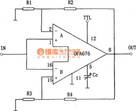
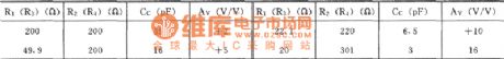


The picture shows the gain programmable amplification circuit. This circuit is mainly made up of OPA676 integrated chip. And the OPA676's internal part has two channels amplification circuit which is marked as A channel and B channel separately (see the A and B in the picture). The two channels' conducting mode or not conducting mode are controlled by the pin 12's voltage level (which is called TTL port). If the TTL port's voltage is high level, the A channel (the higher part of the circuit) would work and the B channel (the lower part of the circuit ) would be not conducted. Otherwise when the TTL port is in low voltage level, the A channel would be not conducted and the B channel would work. The A channel's voltage magnification is AVA=1+R4/R3, and the B channel's voltage magnification is AVB=1+R4/R3. So it could only select different R1, R2 or R3, R4, the A and B channels would have different gain. By controlling the A and B channels selection port TTL's voltage level (pin 12), it could be easy to achieve the gain programmable control. (View)
View full Circuit Diagram | Comments | Reading(656)
Inverse-Counting Digital-Display Timing Controller (CD40110 And CD4040 And CD4069) Circuit
Published:2011/8/4 5:54:00 Author:Robert | Keyword: Inverse-Counting, Digital-Display, Timing, Controller

By using the AC power's 50Hz output frequency for frequency demultiplication, it could get kinds of different frequency's time-base pulses. This circuit uses lmin's time length as the timer's time-base standard. By the counter's counting, decoding and finally the nixietube would display the time. The circuit uses inverse-counting timing mode. The user should firstly predetermine the needed timing time by presetting the switch. Then by the subtraction counting to reduce the predetermined time step by step. When the predetermined time is reduced to 0, the counter would stop counting and output the control signal to make the relay have a action. Bucause the circuit can choose the presetting timing on or timing off, so it is very easy to use. Its circuit is shown in the picture. (View)
View full Circuit Diagram | Comments | Reading(7765)
Timing Circuit Composed Of Quartz Electronic Clock IC
Published:2011/8/4 8:06:00 Author:Robert | Keyword: Timing, Quartz, Electronic Clock, IC

The pulse signal, which provided from the quartz electronic clock IC, has high accuracy. So it is widely used not just in quartz electronic clock, but also in time-base circuit and timing circuit. The picture shows the second pulse signal generator principle circuit composed of quartz electronic clock IC. The IC's working voltage is provided from positive voltage drop of two rectifier diodes (2CP). The power could be selected during 1.5V~15V. And also two detector diodes (2CP) and a triode (3CG) make up the NAND gate logic circuit. When the circuit is working, the output port (triode's collector polar) could get sable and accurate second signal. The circuit is connected a external 32.768kHz quartz crystal and a 5~20pF variable capacitor for frequency micro-adjustment. The quartz electronic clock IC can use the low-frequency type clock circuit, such as H5544 or LH5093 and so on. (View)
View full Circuit Diagram | Comments | Reading(2672)
Low Supply Voltage Thyristor Control Circuit
Published:2011/8/4 9:18:00 Author:Robert | Keyword: Low, Supply, Voltage, Thyristor, Control

This circuit's power supply voltage is 12~16V which can be used in toy trains and other low voltage devices. By using S566B as the trigger circuit which control the conduction of the thyristor. The DC power is provided by rectifier regulator circuit. The R1 is voltage dropping resistor which make the regulator has very low voltage. The middle transistor T1's function is reduce the control dead zone. Because the circuit's loading current is very low, however the bidirectional transistor's current is higher than its maintaining current, it could connect a 1~2W lamp. Because the transformer's output power is very low, in the moment of the conduction of the bidirectional transistor, for the fast increasing current, the transformer's leakage inductance is equivalent to a large series resistor, which would cause a short-term voltage discontinuous case. So it should connect a capacitor C4 in series (dotted line). (View)
View full Circuit Diagram | Comments | Reading(943)
Electric fence control circuit
Published:2011/8/5 2:46:00 Author:Ecco | Keyword: Electric fence control

The electric fence control circuit is composed of the power supply circuit, high voltage circuit and sound and light alarm circuit, and it is shown in Figure 4-26. Power supply circuit is composed of the power switch S, the power transformer Tl, bridge rectifier UR, filter capacitor Cl, current limiting resistor Rl and the voltage regulator diode VS. The high-voltage consists of step-up transformer T2, neon light HL, resistor R3, lighting ELl and the secondary winding of power transformer T3. Sound and light alarm circuit consists of the T3, thyristor VT, diodes VDl, VD2, resistor R2, capacitors C2, C3, potentiometer RP, relay K, AC contactor KM, light EL2 and alarm HA.
(View)
View full Circuit Diagram | Comments | Reading(3863)
500Hz signal generator circuit
Published:2011/8/6 8:17:00 Author:nelly | Keyword: signal generator

2. Working principle is as shown in the picture.
The 500Hz oscillator is composed of VTl, T, VDl, resistor, capacitors and so on. The oscillator frequency is decided by the parallel resonant frequency of C3 and L1-3. Resistor Rl is used to improve the input impedance of the transistor VTl, so the influence to the oscillator also can be reduced. R2, R3 are the DC bias resistors. R4 and R5 are the VTl emitter resistors, and R4 has the current negative feedback function. In order to adapt the change of supply voltage, the voltage of two ends should be regulated. Under normal circumstances, the output level of L4-5 is 0dB±2.6dB/600Ω, and the oscillation frequency is 500Hz.
(View)
View full Circuit Diagram | Comments | Reading(816)
Converter Circuit With Non-Resonant Feature
Published:2011/8/4 10:35:00 Author:Robert | Keyword: Converter, Non-Resonant, Feature

The converters, which are named with part-resonance, multi-resonance, current commutation type and so on, are the zero voltage switch converters with this feature. And the inductance commutation type converter even be used as zero voltage switch in non-resonant mode from the principle, it also has few cases of the surge phenomena. And also it could adjust the voltage by the PWM control. The picture is the basic circuit of this mode. The Lc is the inductance for current commutation. The Cc is the capacitor for cutting the DC power (not for non-resonant using). In this mode, the VT1 and VT2 would alternately and continuously turn on and turn off. (View)
View full Circuit Diagram | Comments | Reading(817)
The simple pulse signal generator circuit composed of 4LS00, 74LS221
Published:2011/8/6 3:10:00 Author:nelly | Keyword: simple, pulse signal, generator

The simple pulse signal generator circuit is as shown. This signal generator mainly uses two TTL ICs (74LS00 and 74LS221) to produce the pulse signal of τ=4μs; Therefore, it uses fewer components, and the maintenance and adjustment will be very simple.
(View)
View full Circuit Diagram | Comments | Reading(1056)
Double pulse generator (HEF4538) circuit
Published:2011/8/6 2:24:00 Author:nelly | Keyword: Double, pulse generator

The double pulse generator (HEF4538) circuit is as shown: (View)
View full Circuit Diagram | Comments | Reading(2502)
Ultra-low frequency pulse generator circuit
Published:2011/8/6 2:50:00 Author:nelly | Keyword: Ultra-low, frequency pulse, generator

The figure shows the Ultra-low frequency pulse generator. The pulse generated by this device has 0.15 to 50s width. (View)
View full Circuit Diagram | Comments | Reading(1069)
The multivibrator with variable duty cycle circuit diagram composed of Schmitt trigger
Published:2011/8/4 1:56:00 Author:Ecco | Keyword: multivibrator, variable duty cycle, Schmitt trigger

It is the multivibrator with variable duty cycle composed of Schmitt trigger CD40106.
(View)
View full Circuit Diagram | Comments | Reading(857)
Black-And-White Wall Hanging Visible Doorbell Circuit
Published:2011/8/5 8:12:00 Author:Robert | Keyword: Black-And-White, Wall, Hanging, Visible, Doorbell


As the people's life level in our country is higher than before, some home security products have entered the house gradually. And the visible doorbell's price is going from the original thounds yuan per set to now hundreds yuan per set. It enters the home with geometric popularizes speed.The home installing the visible doorbell's purpose is to enhance the security. If adding a electromagnetic locks and automatic door closer, the user could enjoy the modern life that control the door to open or close without going out.To assemble a visible doorbell by yourself, it needs the following elements: a 38x35 standard size black-and-white camera, a 4-inch black-and-white display module, outdoor device and indoor device and 18V power case which are totally three sets, two control circuit boards, one power board, several electronic elements, one set of colourful product outer packing. The optional component is listed here: a electric control lock, a automatic door closer. (View)
View full Circuit Diagram | Comments | Reading(813)
The temperature controller 4
Published:2011/8/5 2:24:00 Author:Ecco | Keyword: temperature controller

The temperature controller circuit is composed of the power supply circuit, the temperature detection control circuit and over-temperature alarm circuit, and it is shown as the chart. Power supply circuit is composed of the power transformer T, rectifier diodes VD4 ~ VD7, filter capacitor C3 and Zener VS. Temperature detection control circuit consists of the N1 ~ N3 which are inside of four operational amplifier integrated circuit IC (M ~ N4), resistors R1 ~ R1O, transistors V1 ~ V3, potentiometer RP, thermistor RT, LEDs VL1, VL2, diode VD2 and relay K. VD1 ~ VD3 select 1N4l48 silicon switching diodes; VD4 ~ VD7 select 1 N4007 silicon rectifier diodes.
(View)
View full Circuit Diagram | Comments | Reading(851)
| Pages:591/2234 At 20581582583584585586587588589590591592593594595596597598599600Under 20 |
Circuit Categories
power supply circuit
Amplifier Circuit
Basic Circuit
LED and Light Circuit
Sensor Circuit
Signal Processing
Electrical Equipment Circuit
Control Circuit
Remote Control Circuit
A/D-D/A Converter Circuit
Audio Circuit
Measuring and Test Circuit
Communication Circuit
Computer-Related Circuit
555 Circuit
Automotive Circuit
Repairing Circuit