
Circuit Diagram
Index 599
SATURATED_FLIP_FLOP
Published:2009/7/14 21:24:00 Author:May

Simple circuit shown is preferable at moderate operating temperatures. If emitter triggering is not used, 220-ohm emitter resistor can be removed.- Transistor Manual, Seventh Edition, General Electric Co., 1964, p 186. (View)
View full Circuit Diagram | Comments | Reading(668)
TELEPHONE_CHANNEL_AMPLIFIER
Published:2009/7/14 22:41:00 Author:Jessie


Thick film construction gives 36 db gives and is distortion. free up to 65 mw. Input and output impedances are 600 ohms, for frequency multiplex equipment.-N. A Zellmer, Getting the Most out of Feedback,Electronics,39:2, p 66-72. (View)
View full Circuit Diagram | Comments | Reading(593)
567_ULTRASONIC_RECEIVER
Published:2009/7/14 21:24:00 Author:May

This tunable ultrasonic receiver is ideal for use with the ultrasonic transmitter. It, too, is built around a 567 PLL. (View)
View full Circuit Diagram | Comments | Reading(2910)
100_MC_VRAICAP_OSCILLATOR
Published:2009/7/14 22:40:00 Author:Jessie

Modulator consists of two variable-capacitance diodes in series to r-f and in parallel to audio modulating signals and d-c bias. Frequency deviation is 28 Mc peak-to-peak with modulating signals less thon 28 v and negligible modulating power.-C. Arsem, Wideband F-M with Capacitance Diodes, Electronics, 32:49, p 112-113. (View)
View full Circuit Diagram | Comments | Reading(705)
TWO_TONE_ENCODER
Published:2009/7/14 21:23:00 Author:May

741 opamps and 2N2924 transistors are connected as single-tone encoders producing different audio frequencies、with outputs connected together For2000-Hz tone, use 0.01 μF for c1 and c2 and use 8K for R3 and R4. Formula for frequency of each encoder is f = 0.159/RC where f is in hertz, R in megohms, and C in microfarads; R = R3 = R4 and C = C1 = C2. Frequencies can be chosen for Touch-Tone signaling.-C. D. Rakes, integrated Circuit Projects, Howard W. Sams, Indianapolis, IN, 1975, p 95-97, (View)
View full Circuit Diagram | Comments | Reading(1484)
HI_FI_FET_PREAMP
Published:2009/7/14 22:39:00 Author:Jessie


Breakdown voltage of commercial fet's is extended by using direct.coupled cascade connection with low-cost germanium transistor.-L. J. Sevin, Jr., Field Effect Transistors, McGraw-Hill, N.Y., 1965, p 73. (View)
View full Circuit Diagram | Comments | Reading(1300)
DCTL_FLIP_FLOP
Published:2009/7/14 21:23:00 Author:May

Direct-coupled transistor logic flip-flop utilizes saturation in circuit with extreme simplicity. With silicon transistors, operation up to 150℃ is feasible. Saturation causes storage time delay that limits circuit speed. With germanium transistors, stray voltage signals of about 0.3 v can cause faulty performance.- Transistor Manual, Seventh Edition, General Electric Co., 1964, p 204. (View)
View full Circuit Diagram | Comments | Reading(2242)
ZONED_PUBLIC_ADDRESS_IN_PLANE
Published:2009/7/14 22:38:00 Author:Jessie


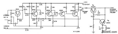
Uses single preamplifier and up to five Power amplifiers and speakers to distribute sound uniformly throughout seating area of plane. Air-ground output switch acts on all amplifiers simultaneously to compensatefor different noise levels on ground than in air,-Transistorized P-A System Adjuststo Aircraft Noise, Electronics, 31:7, p 106-107. (View)
View full Circuit Diagram | Comments | Reading(905)
POWER_FAILURE_ALARM
Published:2009/7/14 21:23:00 Author:May

POWER-FAILURE ALARM-Buzzer sounds and red LED D3 comes on when AC power fails, as reminder that clocks will need resetting. Green LED D1 indicates that alarm is plugged in, D2 is Radio Shack 276-1103 or equivalent silicon diode. B1 is 1.5-6 VDC Radio Shack 273-004 or equivalent buzzer, and K1 is Radio Shack 275-211 or equivalent 117-VAC SPDT relay.-C. R. Graf, The Powerlarm, CQ, Feb. 1977, p 47 and 73. (View)
View full Circuit Diagram | Comments | Reading(0)
1_MC_F_M_OSCILLATOR
Published:2009/7/14 22:38:00 Author:Jessie

Combines Q multiplier with Miller effect to produce simple and stable f-m oscillator and modulator.-P. W. Wood, Transistorized F-M Oscillator, Electronics, 32:5, p 64. (View)
View full Circuit Diagram | Comments | Reading(899)
SATURATED_FLIP_FLOP_FOR_50℃_
Published:2009/7/14 21:23:00 Author:May

Addition of two 33,000-ohm resistors to basic saturated flip-flop boosts temperature range for stable operation above 50℃.- Transistor Manual, Seventh Edition, General Electric Co., 1964, p 186. (View)
View full Circuit Diagram | Comments | Reading(548)
SINGLE_SCS_FLIP_FLOP
Published:2009/7/14 21:22:00 Author:May

Uses only one silicon controlled switch to perform flip-flop function over wide temperature range. Differentiated positive pulses are applied to cathode pate and anode gate alternately to turn scs on and off. If gate leads are brought out separately, circuit can be used as set-reset flip-flop.-E. Koda, Single-SCS Flip-Flop, EEE, 13;2, p 63. (View)
View full Circuit Diagram | Comments | Reading(704)
PLL_ULTRASONIC_GENERATOR
Published:2009/7/14 21:21:00 Author:May
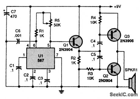
This ultrasonic generator is built around a 567 PLL. By adding a telegraph key, as described in the text, it can be turned into an ultrasonic transmitter. (View)
View full Circuit Diagram | Comments | Reading(2311)
SATURATED_FLIP_FLOP_FOR_100℃_
Published:2009/7/14 21:21:00 Author:May

Increased temperature range is obtained at penalty of smaller voltage change at collector, more battery power consumed, and more trigger power required. Capacitor values depend on trigger characteristics and maximum trigger repetition rate.- Transistor Manual, Seventh Edition, General Electric Co., 1964, p 186. (View)
View full Circuit Diagram | Comments | Reading(599)
4_8_V_WINDOW
Published:2009/7/14 21:21:00 Author:May

CA3098 dual-input precision level detector tells if data input signal is above or below preset levels of 4 and 8 V. Table gives output states for various input levels. Output current can be up to 150 mA.-G. J. Granieri, Precision Level Detector IC Simplifies Control Circuit Design, EDN Magazine, Oct. 5, 1975, p 69-72. (View)
View full Circuit Diagram | Comments | Reading(562)
DIRECT_COUPLED_NOR_GATES
Published:2009/7/14 21:21:00 Author:May

Consists of two epitaxial-transistor nor gates.-D. Hall, Using Epitaxial Transistors in Switching and R-F Circuits, Electronics, 34:13, p 52-53. (View)
View full Circuit Diagram | Comments | Reading(582)
DIRECT_COUPLED_FLIP_FLOP
Published:2009/7/14 21:20:00 Author:May

Typical switching times are 12 millimicrosec for tr and 15 millimicrosec for tf. -Philco MAT Transistors for Logic Circuits up to 5 Mc (Philco ad), Electronics, 33:17, p 50. (View)
View full Circuit Diagram | Comments | Reading(589)
TUNABLE_ULTRASONIC_AMPLIFIER
Published:2009/7/14 21:20:00 Author:May
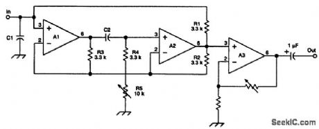
The RF portion of the VLF receiver is shown (a precise rectifier/filter circuit is needed following the output of the figure to generate the dc signal monitored by SID hunters). To tune the SID-hunting frequencies, C2 is 0.001μF. The range of inductance simulated is 10.9 to 43.9 MHz. If C1 is a 0.002-μF unit, then the tuning range is 17 to 34 kHz. (View)
View full Circuit Diagram | Comments | Reading(1321)
DIODE_COUPLED_FLIP_FLOP
Published:2009/7/14 21:20:00 Author:May

Typical switching limes are 20 millimicrosec for tr and 60 millimicrosec for tf. -Philco MAT Transistors for Logic Circuits up to 5 Mc (Philco ad), Electronics, 33:17, p 50. (View)
View full Circuit Diagram | Comments | Reading(651)
RESISTOR_COUPLED_FLIP_FLOP
Published:2009/7/14 21:19:00 Author:May

Typical switching times are 40 millimicrosec for tr and 110 millimicrosec for tf. -Philco MAT Transistors for Logic Circuits up to 5 Mc (Philco ad), Electronics, 33:17, p 50. (View)
View full Circuit Diagram | Comments | Reading(601)
| Pages:599/2234 At 20581582583584585586587588589590591592593594595596597598599600Under 20 |
Circuit Categories
power supply circuit
Amplifier Circuit
Basic Circuit
LED and Light Circuit
Sensor Circuit
Signal Processing
Electrical Equipment Circuit
Control Circuit
Remote Control Circuit
A/D-D/A Converter Circuit
Audio Circuit
Measuring and Test Circuit
Communication Circuit
Computer-Related Circuit
555 Circuit
Automotive Circuit
Repairing Circuit