
Circuit Diagram
Index 583
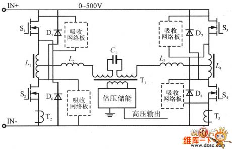
the circuit of improved series resonant converter
Published:2011/7/15 21:45:00 Author:Ariel Wang | Keyword: improved, series, resonant, converter
If y (View)
View full Circuit Diagram | Comments | Reading(740)
the circuit of whether rooster or hen discriminator(1)
Published:2011/7/15 21:46:00 Author:Ariel Wang | Keyword: rooster, hen , discriminator
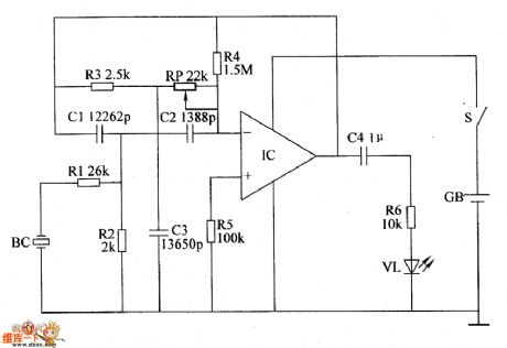
When the mains switch gets through,IC is conducted to work.BC converts the received chickling sound into the electric signal.It filtered the unwanted frequency below 5kHz by the active band-pass filter.It amplifies and outputs needed frequency signal.If the peeping chickling is hen.Then IC outputs voltage with signal.VL is lighted.If the peeping chickling is rooster.Then there is no signal output.VL is not lighted.You can adjust the resistence of RP.It can change the selective frequency of the active band-pass filter.So the identification of whether it's rooster or hen becomes more accurate.
(View)
View full Circuit Diagram | Comments | Reading(533)
the circuit of the automatic anti-frosting controller for crops(2)
Published:2011/7/15 21:46:00 Author:Ariel Wang | Keyword: automatic, anti-frosting , controller , crops
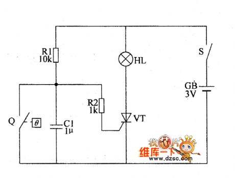
When the atmospheric temperature is higher than +1℃ ,the control contact of the electric contact mercury thermometer Q is connected(the mercury column goes over the control electrode,the mercury connects the control electrode and the contact electrode).The thyristor VT is stopped as the gate outputs low level.When the temperature goes down and the condition of frost is formed,the control contact of the electric contact mercury thermometer Q is disconnected(the mercury column goes beneath the control electrode,the control electrode and contact electrode are disconnected).The gate has the trigger high level.And VT is conducted.There is current passing through in the filament of HL.It lights the gunpowder.The smoking material is inflamed.
(View)
View full Circuit Diagram | Comments | Reading(495)
The circuit of ICS1523 typical application
Published:2011/7/15 21:52:00 Author:Ariel Wang | Keyword: The circuit of ICS1523s typical application
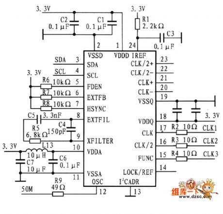
The circuit of ICS1523's typical application is as the chart below.The circuit is monitor controller of SID13806 type.It provides synchronous video signals.The signals are needed when SID13806 connects LCD.ICS1523 inputs 50 MHz (pin 12) .It outputs CLK1(pin 25).CLK2(12.5MHz) and CLK3(387.6kHz) are connected to S1D13806's BUSCLKA (pin 60),CLK1(pin 66),CLK12(PIN 64) and CLK13(pin).
(View)
View full Circuit Diagram | Comments | Reading(641)
the alarm circuit of water break in the spray pipe for seeding-machine(2)
Published:2011/7/15 21:47:00 Author:Ariel Wang | Keyword: alarm , water break , spray pipe , seeding-machine
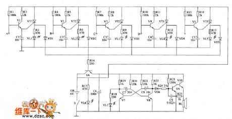
When the mains switch S gets through,the water break detected circuit and the sound and light alarm are conducted to work.When the spray pipe of any circuit is blocked,the SenseFET is conducted as the base electrode becomes high level.The transistor of the circuit is conducted.The LED of the circuit is lighted.It indicates how many the blocked spray pipes are.At the same time,V6 is conducted.The multivibrator and the controlled audio oscillatory circuit are conducted to work.B1 gives out alarm sound.For example,when the spray pipe of circuit A is blocked,there's no water spraying out from the sprayer in circuit A.V1,VT1 and V6 are conducted.VL1 is lighted.VL7 is lighted.BL gives out alarm sound.
(View)
View full Circuit Diagram | Comments | Reading(540)
the alarm circuit of water break in the spray pipe for seeding-machine(1)
Published:2011/7/15 21:50:00 Author:Ariel Wang | Keyword: alarm , water break , spray pipe , seeding-machine
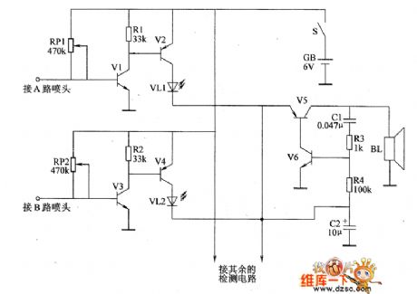
When the mains switch S gets through,the water break detected cicWhen the mains switch S gets through,the water break detected circuit and the sound and light alarm are conducted to work.When the spray pipe of any circuit is not blocked,the base electrode of V1 and V3 are low level.V2,V4~V6 are not conducted.VL1 and VL3\2 are not lighted.BL doesn't give a sound. When the spray pipe of any circuit is blocked.The SenseFET of the circuit is conducted as the base electrode becomes high level.The LED of the circuit is lighted.It indicates how many the blocked spray pipes are.At the same time,the audio oscillatory circuit works.B1 gives out the alarm sound.
(View)
View full Circuit Diagram | Comments | Reading(598)
the fill light circuit of the chicken farm(1)
Published:2011/7/15 21:54:00 Author:Ariel Wang | Keyword: fill light, chicken farm
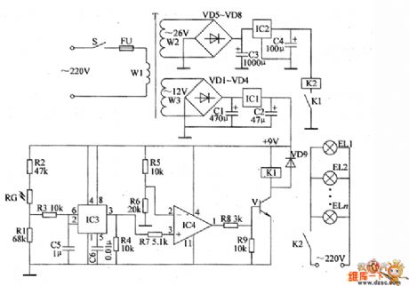
When in daylight,as the sunlight is strong,the resistance of RG is low.The pin-2 and pin-6 output high level.The pin-3 outputs low level.The pin-1 of IC4 outputs low level.V is stopped.K1 and K2 are not pulled in.The floodlights EL1~ELn are not lighted.In the rainy and cloudy day(in the day),the resistance of RC increases.The pin-2 and pin-6 of IC3 output low level.The pin-3 outputs high level.IC4 outputs high level as the voltage of non-inverting input end(pin-3) is higher than the voltage of inverting input end(pin-2).V is conducted.K1 is pulled in.The normally open contacts of K1 are connected.K2 is conducted to pull in.The floodlights EL1~ELn are conducted to be lighted.It provides light for the chicken house.
(View)
View full Circuit Diagram | Comments | Reading(531)
The circuit diagram of high precision and low offset current follower (LM11C, LF351)
Published:2011/8/8 22:11:00 Author:Felicity | Keyword: high precision, low offset, current follower


LM11C has a very low offset current (around 100pA), a low misalignment voltage( around 0.6 mV) and a 110dB CMRR.LF351 operational amplifier has a misalignment voltage about 10mv ,a static current around 3.4mA and a input offset current about 200PA. In this circuit, A2 adopts alternating-current coupling to reduce offset current. And this circuit has a long overload recovery time and the common-mode input voltage cannot exceed ±l0V. (View)
View full Circuit Diagram | Comments | Reading(877)
The circuit diagram of frequency-adjustable band-pass filter (μA748)
Published:2011/8/9 2:40:00 Author:Felicity | Keyword: band-pass filter, frequency-adjustable


The resonant frequency of this filter can be adjusted by in-line potentiometer and Q can remain basically unchanged. Changing the position of the potentiometer is the same as adding a voltage divider. It can reduce the current that in R1, R2 and R3 which can be seen as increasing the resistance of R1, R2 and R3.As the potentiometer changed, the bandwidth and resonant frequency are also changed while Q remains basically unchanged. It’s because that the change of R1, R2, and R3 are the same. Changing the capacity of capacitor C1 can change the work frequency of the filter, but the adjustable extent of the bandwidth is not large. (View)
View full Circuit Diagram | Comments | Reading(951)
ultrasonic insect repellent circuit with CD4017
Published:2011/7/20 23:06:00 Author:chopper | Keyword: ultrasonic, insect repellent

View full Circuit Diagram | Comments | Reading(5091)
quadruplex interlock switch(2) (CD4028、CD40107)circuit
Published:2011/7/20 23:12:00 Author:chopper | Keyword: quadruplex, interlock switch, secondary circuit

View full Circuit Diagram | Comments | Reading(2916)
stair light control switch circuit with CD4028
Published:2011/7/20 23:32:00 Author:chopper | Keyword: stair light, control switch

View full Circuit Diagram | Comments | Reading(2608)
responder (CD4011) circuit with nand gate
Published:2011/7/20 23:43:00 Author:chopper | Keyword: responder circuit, nand gate

Quiz responder is a very typical interlock circuit.As long as one of participates first presses the responder,the others are invalid.The responder shown in the picture can be used for many people to attended the answer,in the circuit there are only two groups.And it can add some groups according to the actual need in the practical usage.And the circuit is shown as picture.Each group of the responders is formed by a answer button, an input control gate, a RS trigger and a luminescent indicator circuit.
(View)
View full Circuit Diagram | Comments | Reading(1443)
eight continuous sound space gun circuit(CD4069,KD9562)
Published:2011/7/22 2:56:00 Author:chopper | Keyword: eight, continuous sound, space gun

KD9562 is a toy phonation circuit which can send out 8 analog sound, and it has 8 trigger ends. Put it in a toy gun, it will send outa analog sound each time users press it.If you use a trigger pulse distributor to trigger its eight trigger ends take turns, it will form a eight sound space gun circuit which can send out continuous sound, the circuit is shown as picture.Circuit consists of eight analog phonation circuit KD9562, trigger pulse generator, pulse distributor,and the trigger pulse inverter. (View)
View full Circuit Diagram | Comments | Reading(2057)
LED sign decorative light(4)
Published:2011/7/25 2:13:00 Author:chopper | Keyword: LED sign, decorative light

This example describes the LED sign decorative light,which can be made into the electronic road sign in theater,dance hall and other public places, as the safe passage in the bathroom. The principle of circuit The LED sign decorative light circuit is formed by the LEDs VL1-VL8, six non-gate integrated circuit IC (D1-D6), resistors B1-R12 and capacitors C1-C5, which is shown in Figure 1-156
The circuit adopts 9V laminated battery,and can also use the regulated power supply formed by capacitor C6, C7, resistor R12, rectifier diodes VD1, VD2 and a voltage-regulator diode VS
(View)
View full Circuit Diagram | Comments | Reading(1822)
LED sign decorative light(3)
Published:2011/7/20 0:13:00 Author:chopper | Keyword: LED sign, decorative light

This example describes light-controlled LED sign decorative light which adopts divided components.And it does not work during the day, and automatically lights up at night, which is of traits like low power consumption, long life, maintenance-free, easy to make and so on. The principle of circuitThe LED sign decorative light circuit is formed by the power supply circuit, light-controlled circuit and LED display circuit,which is shown in Figure 1-155. The power supply circuit is formed by the capacitor C1, rectifier diode VD, voltage regulator diode VS and filter capacitor C2.
(View)
View full Circuit Diagram | Comments | Reading(1940)
LED sign decorative light(2)
Published:2011/7/20 0:44:00 Author:chopper | Keyword: LED sign, decorative light

This example describes the LED sign decorative light,which uses some LEDs to form some words(for example, Please don't spit ). When the power is available, the seven characters light up one by one,finally they form Please do not spit , and then seven characters all turn off,then repeat the next cycle. The principle of circuit The LED sign decorative light circuit is formed by the clock generator, count distributor and LED display drive circuit, which is shown in Figure 1-154
(View)
View full Circuit Diagram | Comments | Reading(892)
LED sign decorative light(1)
Published:2011/7/20 4:45:00 Author:chopper | Keyword: LED sign, decorative light

This example describes the LED sign decorative light,which is used to decorate all kinds of doors mark,road sign and emergency exit,fire access and other signs, and it can produce effects like text flashing,border flowing,and it will play a role of eye-catching, decorative effects. The principle of circuitThe LED sign decorative light circuit is formed by the power supply circuit,light flowing control circuit and text flashing control circuit, which is shown in Figure 1-153. Power supply circuit is formed by the rectifiers diodes VD1-VD5, resistor R1, voltage regulator diode VS and filter capacitor C1, C4.
(View)
View full Circuit Diagram | Comments | Reading(1560)
irrigation motor automatic protector (2)
Published:2011/7/20 4:51:00 Author:chopper | Keyword: irrigation motor, automatic protector

Rural irrigative pump motor often be burned due to low voltage or phase lack when it runs.This example describes the irrigation motor automatic protector, which can cut off three-phase AC power supply to protect the motor when the phase is lack. The principle of circuitThe irrigation motor automatic protection circuit is formed by the start control circuit, phase-lack control circuit and test circuit,which is shown in Figure 4-97. Start circuit is formed by the start button S2 (S2a, S2b), AC contactor KM and relay K2,etc.
(View)
View full Circuit Diagram | Comments | Reading(964)
irrigation motor automatic protector (1)
Published:2011/7/20 0:30:00 Author:chopper | Keyword: irrigation motor, automatic protector

The principle of circuitThe irrigation motor automatic protector circuit is formed by the power supply circuit and the detection/protection control circuit, which is shown in Figure 4-96. Power supply circuit is formed by the power transformer T, rectifier diodes VD1-VD4 and filter capacitor C1. Detection/protection control circuit is formed by the detection electrodes A,B,start button S,resistors R1-R4, capacitor C2, optical coupler VLC, bi-directional trigger diode V, thyristor VT, electronic switch integrated circuit IC and AC contactor KM.
(View)
View full Circuit Diagram | Comments | Reading(1477)
| Pages:583/2234 At 20581582583584585586587588589590591592593594595596597598599600Under 20 |
Circuit Categories
power supply circuit
Amplifier Circuit
Basic Circuit
LED and Light Circuit
Sensor Circuit
Signal Processing
Electrical Equipment Circuit
Control Circuit
Remote Control Circuit
A/D-D/A Converter Circuit
Audio Circuit
Measuring and Test Circuit
Communication Circuit
Computer-Related Circuit
555 Circuit
Automotive Circuit
Repairing Circuit