Measuring and Test Circuit
ZERO_POINT_WITH_OVERVOLTAGE_PROTECTION
Published:2009/7/14 21:37:00 Author:May | From:SeekIC
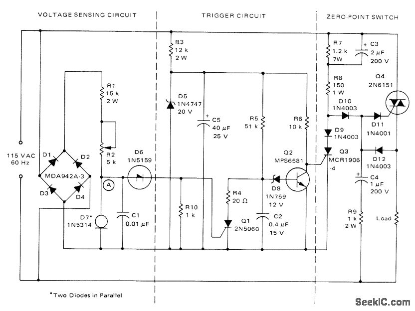
Used to protect voltage-sensitive load from excessive line voltage Switch section operates conventionally to turn on triac almost immediately after each zero crossing between half-cycles,For normal line voltages, SCR Q3 is off. When overvoltage condition is sensed during any half-cycle, SCR Q1 s turned on, discharging C2 and turning Q2 off. This allows Q3 to turn on and divert triac gate drive, removing power from load As long as overvoltage condition exists, Q1 is turned on each half-cycle and C2 is unable to charge enough to turn Q2 on,When overvoltage condition ceases, C2 charges to voltage set by D8 in about 20 ms, saturatingQ2 so Q3 turns off and Q4 turns on R2 can be set to allow line voltage variations from almost 0 to 11 v.-“Circuit Applications for the Triac,” Motorola, Phoenix, AZ, 1971, AN-466, p 14.
Reprinted Url Of This Article:
http://www.seekic.com/circuit_diagram/Measuring_and_Test_Circuit/ZERO_POINT_WITH_OVERVOLTAGE_PROTECTION.html
Print this Page | Comments | Reading(3)

Article Categories
power supply circuit
Amplifier Circuit
Basic Circuit
LED and Light Circuit
Sensor Circuit
Signal Processing
Electrical Equipment Circuit
Control Circuit
Remote Control Circuit
A/D-D/A Converter Circuit
Audio Circuit
Measuring and Test Circuit
Communication Circuit
Computer-Related Circuit
555 Circuit
Automotive Circuit
Repairing Circuit
Code: