Basic Circuit
SIMPLE_ALL_PASS_FILTER
Published:2009/7/14 21:53:00 Author:Jessie | From:SeekIC


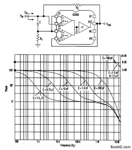
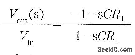
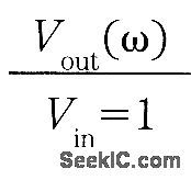
A very simple all-pass implementation can be realized with an active-feedback amplifier like the AD830 or the LTC1193. R1 and C set the filter’s actual transfer function, while R2 is needed to provide a purely real input impedance over the frequency range of the AD830 (necessary for measurement reasons). The filter’s two basic equations are and from which we can see that the magnitude is constant:and the phase of Vout/Vin as a function of ω is 180°-2 tan-1 (ωCR1)From the first equation, it's clear that for Zin to be purely real, R1 has to be equal to R2/2, which implies Zin=R1. Once C is chosen, R1 and R2 can be picked according to the termination and required phase shift. The graph shows the circuit's performance for Vs=±15V, R1=100,R2=200, and values of C from 1.5 μF to 150 pF with 90° phase shifts at one-decade increments up to 10 MHz.
Reprinted Url Of This Article:
http://www.seekic.com/circuit_diagram/Basic_Circuit/SIMPLE_ALL_PASS_FILTER.html
Print this Page | Comments | Reading(3)

Article Categories
power supply circuit
Amplifier Circuit
Basic Circuit
LED and Light Circuit
Sensor Circuit
Signal Processing
Electrical Equipment Circuit
Control Circuit
Remote Control Circuit
A/D-D/A Converter Circuit
Audio Circuit
Measuring and Test Circuit
Communication Circuit
Computer-Related Circuit
555 Circuit
Automotive Circuit
Repairing Circuit
Code: