Automotive Circuit
Automotive Braking Air Under Pressure Protector One
Published:2011/7/29 4:15:00 Author:Felicity | Keyword: Automotive Braking, Air Under Pressure Protector | From:SeekIC


Work of the circuit
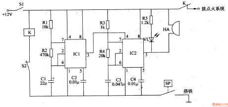
The circuit consists of control implementation circuit, low-frequency oscillator, audio oscillator, the pressure sensor SP, relay K and light and sound show circuit. (It is showed in picture 7-154.)
Control implementation circuit consists of relay K and clutch switch S2.
Low-frequency oscillator consists of time-base integrated circuit ICl, resistors Rl and R2 and capacitors Cl and C2.
Audio oscillator consists of time-base integrated circuit lC2, resistors R3 and R4 and capacitors C3 and C4.
Light and sound show circuit consists of resistor R5, light-emitting diodes VL and piezoelectric buzzer HA.
When the pressure of the reservoir is above the safe braking pressure, the contact inside pressure sensor SP releases and this protector doesn’t work.
When the pressure of the reservoir is under the safe braking pressure, the contact inside pressure sensor SP closes, and the low frequency and audio frequency oscillator are both at work (the low frequency oscillator modulate the audio frequency oscillator) to make VL shine and HA sends out alarm. At the same time , relay K closes , and the normally close contact releases to cut off the +12V power of the ignition system and the engine stops.
Reprinted Url Of This Article:
http://www.seekic.com/circuit_diagram/Automotive_Circuit/Automotive_Braking_Air_Under_Pressure_Protector_One.html
Print this Page | Comments | Reading(3)

Article Categories
power supply circuit
Amplifier Circuit
Basic Circuit
LED and Light Circuit
Sensor Circuit
Signal Processing
Electrical Equipment Circuit
Control Circuit
Remote Control Circuit
A/D-D/A Converter Circuit
Audio Circuit
Measuring and Test Circuit
Communication Circuit
Computer-Related Circuit
555 Circuit
Automotive Circuit
Repairing Circuit
Code: