Automotive Circuit
Automotive Braking Air Under Pressure Protector Three
Published:2011/7/29 3:58:00 Author:Felicity | Keyword: Automotive Braking, Air Under Pressure Protector | From:SeekIC


Work of the circuit
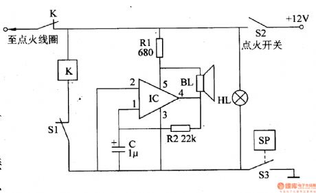
The circuit consists of speaker BL, voltage indicator HL, self-excited audio oscillator, the clutch switch S1, S2 and pressure sensing ignition switch S3. (It is showed in picture 7-155.)
Self-excited audio oscillator consists of power electronic switch IC IC (includes regulator, zoom, comparator, select 'pass to the ignition coil, plastic and power output and other circuits) and the resistors Rl and R2, capacitor C.
This automotive braking air under pressure protector consists of speaker BL, under pressure indicator HL, audio oscillator, clutch switch S1, ignition switch S2 and air pressure sensor switch S3.
When the braking pressure is normal, the contact inside S3 releases and this protector doesn’t work.
When the braking pressure is low, the contact inside S3 closes to make K closes too. And the normally close contact releases to cut off the power of the ignition system and the engine stops. At the same time, the under pressure indicator HL is on; the self-excited audio oscillator works; the speaker BL sends out alarm.
Reprinted Url Of This Article:
http://www.seekic.com/circuit_diagram/Automotive_Circuit/Automotive_Braking_Air_Under_Pressure_Protector_Three.html
Print this Page | Comments | Reading(3)

Article Categories
power supply circuit
Amplifier Circuit
Basic Circuit
LED and Light Circuit
Sensor Circuit
Signal Processing
Electrical Equipment Circuit
Control Circuit
Remote Control Circuit
A/D-D/A Converter Circuit
Audio Circuit
Measuring and Test Circuit
Communication Circuit
Computer-Related Circuit
555 Circuit
Automotive Circuit
Repairing Circuit
Code: