Automotive Circuit
Automotive Braking Air Under Pressure Protector Two
Published:2011/7/29 4:00:00 Author:Felicity | Keyword: Automotive Braking, Air Under Pressure Protector | From:SeekIC


Work of the circuit
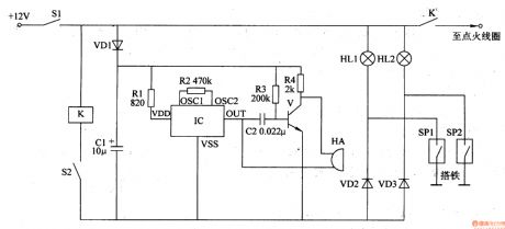
The circuit consists of air pressure sensor SPl, oil pressure sensor SP2, auto ignition switch Sl, clutch switch S2, buzzer HA, relay K, audio integrated circuit IC, transistor V, diode VDl-VD3, resistors Rl-R4, capacitors Cl and C2 and light HLl and HL2. (It is showed in picture 7-154.)
When the pressure of the braking air and the engine oil is normal, the contacts inside sensor SP1 and sensor SP2 releases. This circuit stands by.
When the pressure of the braking air and the engine oil is low, the contact inside sensor SP1 or sensor SP2 closes to make HL1 and VD2 or HL2 and VD3 on. And the relay K closes and the normally close contact cut off the +12V work power to extinguish the engine. At the same time IC works to make HA send out alarm.
Reprinted Url Of This Article:
http://www.seekic.com/circuit_diagram/Automotive_Circuit/Automotive_Braking_Air_Under_Pressure_Protector_Two.html
Print this Page | Comments | Reading(3)

Article Categories
power supply circuit
Amplifier Circuit
Basic Circuit
LED and Light Circuit
Sensor Circuit
Signal Processing
Electrical Equipment Circuit
Control Circuit
Remote Control Circuit
A/D-D/A Converter Circuit
Audio Circuit
Measuring and Test Circuit
Communication Circuit
Computer-Related Circuit
555 Circuit
Automotive Circuit
Repairing Circuit
Code: