Automotive Circuit
Automotive Braking Air Under Pressure Protector Four
Published:2011/7/29 3:48:00 Author:Felicity | Keyword: Automotive Braking, Air Under Pressure Protector | From:SeekIC

Work of the circuit
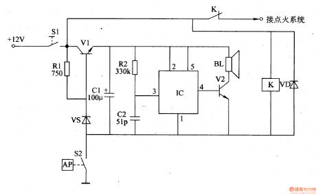
The circuit consists of pressure measurement and control circuit, voltage regulator filter circuit and voice alarm circuit. (It is showed in picture 7-156.)
Pressure measurement and control circuit consists of air pressure sensing switch S2, the ignition switch Sl, the relay K and diode VD.
Voltage regulator filter circuit consists of transistor Vl, resistors Rl, voltage regulator diode VS and filter capacitor Cl.
Voice alarm circuit consists of voice integrated circuit IC, resistor anal, capacitor C2, transistor V2 and the speaker BL.
When the braking pressure is normal, the contact inside S2 releases and this protector doesn’t work. The +12V power supplies for the ignition system through ignition switch S1 and the normally close contact of K.
When the braking pressure is below 25N/cm2, the contact of S2 closes to make K on. And the normally close contact releases to cut off the power of the ignition system and the engine stops. At the same time, after being regulated by V1, VS and smoothed by C1, the +12V voltage supplies IC for 3V direct work voltage. When IC is on, the vocal electrical signal output by pin 4 is amplified by V2 to drive BL to send out “Be care of the air pressure” voice.
Reprinted Url Of This Article:
http://www.seekic.com/circuit_diagram/Automotive_Circuit/Automotive_Braking_Air_Under_Pressure_Protector_Four.html
Print this Page | Comments | Reading(3)

Article Categories
power supply circuit
Amplifier Circuit
Basic Circuit
LED and Light Circuit
Sensor Circuit
Signal Processing
Electrical Equipment Circuit
Control Circuit
Remote Control Circuit
A/D-D/A Converter Circuit
Audio Circuit
Measuring and Test Circuit
Communication Circuit
Computer-Related Circuit
555 Circuit
Automotive Circuit
Repairing Circuit
Code: