Signal Processing
FLOWMETER_FREQUENCY_CONVERTER
Published:2009/7/14 22:01:00 Author:Jessie | From:SeekIC

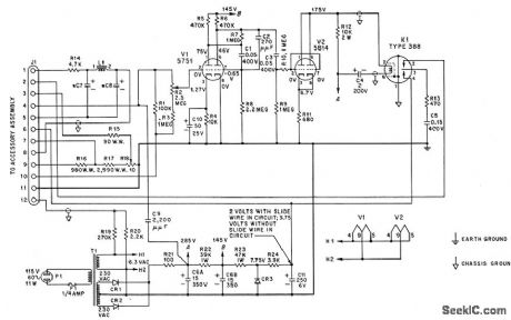
Provides output signal that is directly provides output signal that is directly proportional to frequency of input from ,turbine flow-sensing element, for driving associated electronic potentiometer. V1 and V2 form three-stage limiting amplifier. Capacitor tachometer circuit uses chopper K1 to discharge C5 repetitively through adjustable-range resistor. Adjustable precision resistor in series with slide-wire of potentiometer provides accurate manual compensation for changes in specific gravity of measured medium. Circuit is Potter model 11-B frequency converter.-G. C. Carrol, Industrial Instrument Servicing Handbook, McGraw-Hill, N.Y., 1960, p 3-3.
Reprinted Url Of This Article:
http://www.seekic.com/circuit_diagram/Signal_Processing/FLOWMETER_FREQUENCY_CONVERTER.html
Print this Page | Comments | Reading(3)

Article Categories
power supply circuit
Amplifier Circuit
Basic Circuit
LED and Light Circuit
Sensor Circuit
Signal Processing
Electrical Equipment Circuit
Control Circuit
Remote Control Circuit
A/D-D/A Converter Circuit
Audio Circuit
Measuring and Test Circuit
Communication Circuit
Computer-Related Circuit
555 Circuit
Automotive Circuit
Repairing Circuit
Code: