
Circuit Diagram
Index 1714
AC high voltage generator
Published:2011/6/20 6:46:00 Author:Lucas | Keyword: AC, high voltage , generator

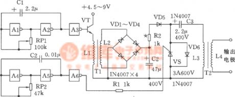
The chart shown as the chart is the AC high voltage generator. It uses AC 220V input directly , and it has the features of with small size, high efficiency, long working time, high output current and so on. A type can work continuously for longer than five minutes, B type can work in long hours. Component selection: VD1 ~ VD4 use 1N4007 diodes, C1 uses 10μF/400V dielectric capacitor; C2 uses nonpolar 0.47μF/450V capacitor; R1 uses the 10k/5W resistor; R2 uses the 1/8W 10K resistor, R3 uses the 1/8W 1.6MΩ ~ 1.8MΩ resistor, VS uses the 3A/400V unidirectional thyristor, C3 ~ C5 use high pressure lOOp/14kV ceramic capacitors, C6 selects the lOOOp/40kV capacitor with engineering plastic shell.
(View)
View full Circuit Diagram | Comments | Reading(757)
Low-power high-performance high-voltage generator
Published:2011/6/20 6:18:00 Author:Lucas | Keyword: Low-power , high-performance, high-voltage , generator
The chart shown as the chart is the low-power high-performance high-voltage generator. It uses CMOS integrated circuits, it has the features of simple current, small operating current (about several hundred mA), reliable working. It is suitable for electric batons, electric fences and many other uses.
(View)
View full Circuit Diagram | Comments | Reading(554)
duplex filter for direct conversion receiver circuit
Published:2011/6/21 0:08:00 Author:John | Keyword: duplex filter, direct conversion receiver

Duplex filter for direct conversion receiver circuit is shown.
(View)
View full Circuit Diagram | Comments | Reading(849)
6C16A headphone amplifier circuit diagarm
Published:2011/6/21 5:38:00 Author:Lucas | Keyword: headphone, amplifier

Output power: ≥ 0.5w; sensitivity: 0.5V; Distortion: ≤%; Frequency: 15Hz ~ 80KHz 1dB; noise: ≤ 1mV; output impedance: 32,64,120,250,300,600 Ω. (View)
View full Circuit Diagram | Comments | Reading(533)
Simple doubler generator
Published:2011/6/19 2:59:00 Author:Lucas | Keyword: Simple, doubler, generator
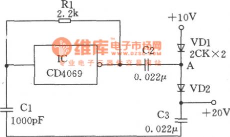
The simple doubler circuit composed of CMOS NOT gate is shown as the chart. The IC in the chart is the inverter and the inverter, Rl, Cl form a square wave oscillator with the frequency about l00kHz, and the oscillator output changes between 0 ~ 10V. When the output is 0V, the capacitor charges to 10V by VD1, when oscillator output changes into +10 V from 0V in a sudden, because the voltage across the capacitor can not change suddenly, the A end of capacitor C2 should be improved accordingly to +20 V, then VDl is reverse-biased, and the current through the VD2 charge to C3, so the output end gets +20 V voltage. But taking into account the diode has voltage drop, so the actual output is slightly lower than +20 V.
(View)
View full Circuit Diagram | Comments | Reading(615)
JFET double-balanced mixer circuit
Published:2011/6/21 0:08:00 Author:John | Keyword: double-balanced mixer

JFET double-balanced mixer circuit is shown.
(View)
View full Circuit Diagram | Comments | Reading(1353)
Eastcom EL610 cell phone failure repair circuit
Published:2011/6/21 0:09:00 Author:John | Keyword: cell phone

Eastcom EL610 cell phone failure repair circuit is shown.
(View)
View full Circuit Diagram | Comments | Reading(806)
12V power supply 30W-50W subwoofer circuit
Published:2011/6/21 0:09:00 Author:John | Keyword: subwoofer
12V power supply 30W-50W subwoofer circuit is shown.
(View)
View full Circuit Diagram | Comments | Reading(3564)
Electric arc welding generator
Published:2011/6/19 2:46:00 Author:Lucas | Keyword: Electric arc welding , generator

The maximum input of the circuit shown as the chart is less than 100W, and it uses the weak current arc technology to automatically ignite quickly about 5mm ~ 10mm, l ~ 3A stable arc. It is used as DC arc welding machine, which can improve arc welder success rate from 30% to l00% to solve the arc problem. The electric arc is difficult to extinguish, and arc welding does not occur the same piece stick welding. The device itself can also be used as a pocket-sized welder to do the welding of lmm metal shell, wire, capillaries, joints and so on.
(View)
View full Circuit Diagram | Comments | Reading(5149)
NE-502 varactor tuning input circuit
Published:2011/6/19 5:09:00 Author:John | Keyword: varactor, tuning input

The following figure is a tuning input circuit which achieves tuning function by variable voltage capacitance diode (varactor). The total tuning capacitance in parallel consists of adjusting capacitanc C1, fixed capacitanc C2 and varactor diode’s junction capacitance D1. The total tuning capacitance is connected with transformer secondary coil L2 in order to form the resonant circuit. In order to reduce the impact of the series combination of capacitor C3/CD1, setting value of capacitor C3 is usually larger than that of the diode. In other cases, in order to make the diode capacitance become a part of resonant circuit’s capacitor, the value of capacitor C3 is very close to that of the diode. (View)
View full Circuit Diagram | Comments | Reading(1086)
Pocket television signal generator
Published:2011/6/21 5:33:00 Author:Lucas | Keyword: Pocket, television , signal generator
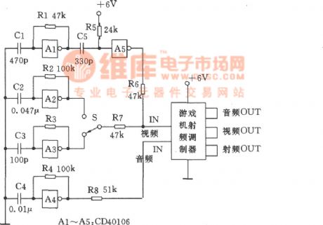
The television signal generator composed of a game RF modulator and a piece of CMOS integrated circuit is shown as the chart. In the Figure: Schmitt triggers Al ~ A4 and RC components form the line sync, horizontal, vertical, and audio signal oscillator. S is used to select the horizontal, vertical signal. A5 and differential circuit C5, R5 will shape the line sync signal in 5 ~ 7μs positive narrow pulse, which will be sent into the RF modulator with horizontal, vertical signal. The power can use the 6V cascading battery.
(View)
View full Circuit Diagram | Comments | Reading(499)
The wiring diagram of DS8 100V,5A universal inducted three-phase three-wire meter
Published:2011/6/20 5:24:00 Author:Lucas | Keyword: wiring diagram , 100V, 5A , universal , inducted , three-phase, three-wire, meter
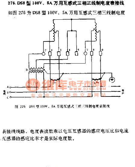
The wiring diagram of DS8 100V,5A universal inducted three-phase three-wire meter is shown as the chart. The meter reading multiplied by the induced voltage ratio of voltage transformer and induced ratio of current transformer is the actual kWh.
(View)
View full Circuit Diagram | Comments | Reading(913)
Mazda 95TAURUS (3.2L, SHO) air-conditioning fan circuit
Published:2011/6/21 0:36:00 Author:John | Keyword: air-conditioning fan

Mazda 95TAURUS (3.2L, SHO) air-conditioning fan circuit is shown.
(View)
View full Circuit Diagram | Comments | Reading(554)
Mazda 95TAURUS (3.0L, SHO) lamp monitor circuit
Published:2011/6/21 0:36:00 Author:John | Keyword: lamp monitor

Mazda 95TAURUS (3.0L, SHO) lamp monitor circuit is shown.
(View)
View full Circuit Diagram | Comments | Reading(671)
Simple transistor IF amplifier circuit
Published:2011/6/17 9:49:00 Author:John | Keyword: transistor, IF amplifier

A simple IF amplifier is just as shown in the figure. AM band radio may have such a circuit, but FM receiver, shortwave receivers and other types of communications receivers may have two to four such circuits.
figure: Simple transistor IF amplifier circuit (View)
View full Circuit Diagram | Comments | Reading(3397)
MC-1350P preamplifier circuit
Published:2011/6/21 0:26:00 Author:John | Keyword: preamplifier
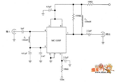
MC-1350P preamplifier circuit is shown.
(View)
View full Circuit Diagram | Comments | Reading(918)
Wiring diagram of DX8 100V,5A universal inducted three-phase three-wire 60 °no-power meter
Published:2011/6/20 5:34:00 Author:Lucas | Keyword: Wiring diagram , 100V, 5A, universal , inducted , three-phase, three-wire , 60°, no-power, meter
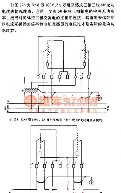
Wiring diagram of DX8 100V,5A universal inducted three-phase three-wire 60 °no-power meter is shown as the chart 278.It is used to adjust the reactive power of AC 50HZ three-phase system circuit. The wiring is actual connected according to the positive phase sequence of three-phase AC. The meter reading multiplied by the ratio of current transformer and the voltage ration of voltage transformer is the actual reactive power degree.
(View)
View full Circuit Diagram | Comments | Reading(957)
transistor pre-amplifier with feedback NPN circuit
Published:2011/6/17 9:37:00 Author:John | Keyword: transistor, pre-amplifier
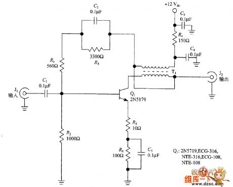
RF amplifier has very versatile functions, which can be used as the receiver’s preamplifier working in the 3 ~ 30MHz short wave band. It also can be used as post amplifier for filter, mixer and other equipment with band attenuation factor. Mixers and crystal filters often have 5 ~ 8dB loss of signal (called insertion loss), then the amplifier can overcome these losses. Meanwhile, the amplifier can also improve oscillator circuit’s output level of the signal generator. In this section, it can be used alone in a separate shielded container and also can be included as a part of the oscillator circuit.
(View)
View full Circuit Diagram | Comments | Reading(1015)
The wiring diagram of MF52 multimeter
Published:2011/6/20 6:03:00 Author:Lucas | Keyword: wiring diagram , multimeter
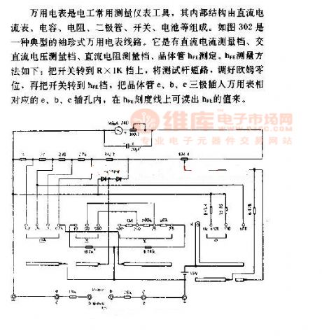
Multimeter is usual a instrument tool for electrician, and its internal structure is composed of the DC ammeter, capacity,resistor, diode, switch, battery. Figure 302 is a typical pocket multimeter lines. It tested by DC current measurement file, AC voltage measurement file, DC resistor measurement file, the transistor hfE. HfE measurement method is shown as follow: the switch is turned the R × 1K file and the stick gage is in the short circuit, then the zero ohms shold be adjusted. Then the switch is turned to hfE file, and the e, b, c poles of transistor are connected to the corresponding to e, b, c jacks of meter.
(View)
View full Circuit Diagram | Comments | Reading(542)
cascode amplifier active preselector circuit
Published:2011/6/17 4:50:00 Author:John | Keyword: cascode amplifier, active preselector

The following picture shows the circuit with a cascode VHF pre-amplifier formed by two pieces of JFET. (It means that Q1 is the direct coupling between the input common-source connection and the output gate connection Q2). In order to avoid the occurrence of self-oscillation circuit, the capacitor (NEUT) is inducted. Capacitance value is tuned to ensure that oscillation would not occur in any frequency circuit of the band-pass. In general, the circuit can be adjusted to a single channel through L2/C1 and L3/C3.
(View)
View full Circuit Diagram | Comments | Reading(1815)
| Pages:1714/2234 At 2017011702170317041705170617071708170917101711171217131714171517161717171817191720Under 20 |
Circuit Categories
power supply circuit
Amplifier Circuit
Basic Circuit
LED and Light Circuit
Sensor Circuit
Signal Processing
Electrical Equipment Circuit
Control Circuit
Remote Control Circuit
A/D-D/A Converter Circuit
Audio Circuit
Measuring and Test Circuit
Communication Circuit
Computer-Related Circuit
555 Circuit
Automotive Circuit
Repairing Circuit