
Circuit Diagram
Index 1715
azda 96TAURUS electric suspension circuit
Published:2011/6/21 0:28:00 Author:John | Keyword: electric suspension

azda 96TAURUS electric suspension circuit is shown.
(View)
View full Circuit Diagram | Comments | Reading(585)
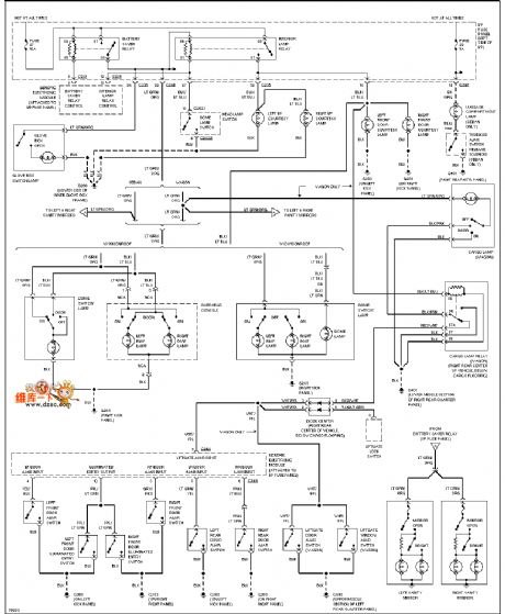
Mazda 96TAURUS lamp monitor circuit
Published:2011/6/21 0:28:00 Author:John | Keyword: lamp monitor

Mazda 96TAURUS lamp monitor circuit is shown.
(View)
View full Circuit Diagram | Comments | Reading(636)
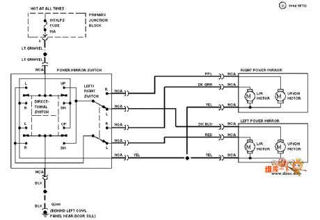
Mazda 96TAURUS power window circuit
Published:2011/6/21 0:29:00 Author:John | Keyword: power window

Mazda 96TAURUS power window circuit is shown.
(View)
View full Circuit Diagram | Comments | Reading(657)
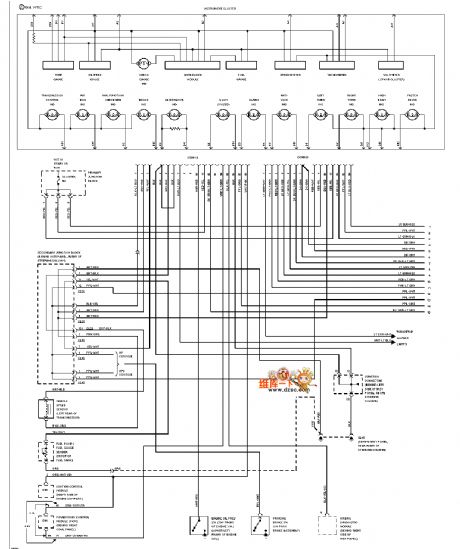
Mazda 96TAURUS (3.0L) instrument panel circuit
Published:2011/6/21 0:29:00 Author:John | Keyword: instrument panel

Mazda 96TAURUS (3.0L) instrument panel circuit is shown.
(View)
View full Circuit Diagram | Comments | Reading(605)
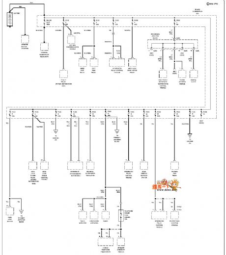
Mazda 96TAURUS (with DRL) automatic light relay circuit
Published:2011/6/21 0:29:00 Author:John | Keyword: automatic light, relay

Mazda 96TAURUS (with DRL) automatic light relay circuit is shown.
(View)
View full Circuit Diagram | Comments | Reading(653)
Mazda 96TAURUS gate controlling light circuit
Published:2011/6/21 0:29:00 Author:John | Keyword: gated controlling light
Mazda 96TAURUS gate controlling light circuit is shown.
(View)
View full Circuit Diagram | Comments | Reading(570)
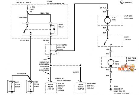
Mazda 94THUNDERBIRD dashboard circuit
Published:2011/6/21 0:22:00 Author:John | Keyword: dashboard
Mazda 94THUNDERBIRD dashboard circuit is shown.
(View)
View full Circuit Diagram | Comments | Reading(570)
Mazda 94THUNDERBIRD power supply circuit
Published:2011/6/21 0:23:00 Author:John | Keyword: power supply
Mazda 94THUNDERBIRD power supply circuit is shown.
(View)
View full Circuit Diagram | Comments | Reading(545)
Mazda 94THUNDERBIRD luggage compartment and throttle opening circuit
Published:2011/6/21 0:23:00 Author:John | Keyword: luggage compartment, throttle
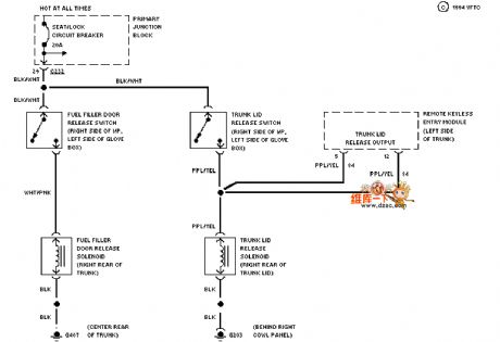
Mazda 94THUNDERBIRD luggage compartment and throttle opening circuit is shown.
(View)
View full Circuit Diagram | Comments | Reading(551)
Mazda 94THUNDERBIRD defogger circuit
Published:2011/6/21 0:23:00 Author:John | Keyword: defogger
Mazda 94THUNDERBIRD defogger circuit is shown.
(View)
View full Circuit Diagram | Comments | Reading(560)
Mazda 94THUNDERBIRD speaker circuit
Published:2011/6/21 0:23:00 Author:John | Keyword: speaker
Mazda 94THUNDERBIRD speaker circuit is shown.
(View)
View full Circuit Diagram | Comments | Reading(570)
Receiver input network equivalent circuit
Published:2011/6/21 0:23:00 Author:John | Keyword: Receiver, input net
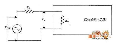
Receiver input network equivalent circuit is shown. (View)
View full Circuit Diagram | Comments | Reading(418)
SL56OC IF amplifier circuit
Published:2011/6/17 10:51:00 Author:John | Keyword: IF amplifier

A tuning circuit is as shown in the following. Tuned circuit T1 is used to replace the original input circuit. Output circuit is replaced with the transformer T2. Besides, V + terminal circuit here uses a Zener diode to rectifier the DC voltage.
figure: SL56OC IF amplifier circuit (View)
View full Circuit Diagram | Comments | Reading(688)
SL-560C IF amplifier circuit
Published:2011/6/17 10:46:00 Author:John | Keyword: IF amplifier

SL560C is basically a gain block that can be used in RF and IF frequency area. Figure shows a circuit based on SL560C. SL560C is the single-ended output circuit transferred by differential input. And the used input end needs to be set by the bypass of capacitor C3. Since this is a broadband circuit, the input or output circuit has no tuning function. The input circuit includes a 0.02μF input coupling capacitor and an RF choke (RFC1).
figure: SL-560C IF amplifier circuit (View)
View full Circuit Diagram | Comments | Reading(1331)
MC-1590 IF amplifier circuit
Published:2011/6/17 10:40:00 Author:John | Keyword: IF amplifier

The picture shows the amplifier based on chips 1490 and 1590. The circuit can work well in the VHF region (30 ~ 80MHz). Input signal can be coupled to the IC through the capacitor C1. Tuning performance can be achieved by the parallel resonant circuit formed by C2 and L1. Capacitor C3 can apply the not used differential input end of chip 1590 to be AC grounded.
The output tuning reflects the differential output characteristics of chip 1590. As for LC tuned circuit, a parallel resonant circuit formed by the T1’s primary coil and capacitor C6 is connected between pin 5 and pin 6.
(View)
View full Circuit Diagram | Comments | Reading(2228)
Cascade amplifier circuit
Published:2011/6/17 9:56:00 Author:John | Keyword: Cascade amplifier
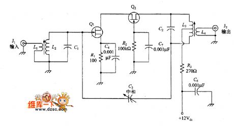
Cascade amplifier is as shown in the figure. The amplifier uses two transistors (both JFET). Q1 is common source configuration and Q2 is a total gate configuration. These two tubes are direct-coupled with each other. The input and output is tuned by a pair of LC filter. (L2C1Ct and L3C2). To avoid the occurrence frequency oscillation in the circuit, a capacitor (C3) 9 is connected to LC filter between the input end of Q1 and the output end of Q2.
figure: Cascade amplifier circuit (View)
View full Circuit Diagram | Comments | Reading(1608)
Three-phase waveform generator composed of CD4017
Published:2011/6/20 6:13:00 Author:Lucas | Keyword: Three-phase , waveform , generator
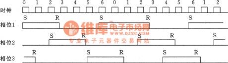
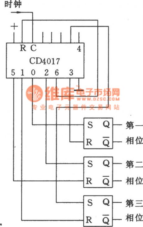
The circuit shown as the chart can use single-phase square wave three-phase to produce square wave, and the three-phase output frequency range is only limited by the logic capacity. Output frequency is 1 / 6 of the input frequency. As bistable flip-flop can change the waveform, the actual input waveform may not be square wave. In the figure, CD4017 is the decimal output CMOS counter with reset function. When the counting resets to 6:00, and then starts counting to six.
(View)
View full Circuit Diagram | Comments | Reading(4382)
Digital acquisition circuit
Published:2011/6/19 2:19:00 Author:John | Keyword: Digital acquisition

This system provides digital acquisition. Digital acquisition circuit is relatively simple and the concrete digital acquisition circuit is shown in the figure.
It can be seen from the figure, Q200 FET is used as a switch to start or stop collecting digital data acquisition. Circuit uses diodes for ESD protection. Digital's I or 0 is equivalent to the on –and-off of the circuit. Therefore, high and low electricuty on the digital capture input end can be generated, aiming to achieve digital collection tasks.
figure: Digital acquisition circuit (View)
View full Circuit Diagram | Comments | Reading(438)
Analog acquisition circuit
Published:2011/6/19 2:11:00 Author:John | Keyword: Analog acquisition

The main features that the analog front-end system is the sensor, which sent the standard signal (ie, 4mA ~ 20mA). This design has certain versatility. As long as the front-end connection is with different sensors, different signal sources can be collected. As the reference for the A / D converter is voltage, which refers that the reference source is the voltage, the A / D achieves voltage conversion. Such requires the conversion from a current signal to a voltage signal. The picture shows the concrete analog acquisition circuit.
It can be seen from the figure that the acquisition circuit convert a current signal into a voltage signal through a resistor. In order to improve the progress of collection, high-precision resistors are needed. Resistors with 1% precision is used here.
(View)
View full Circuit Diagram | Comments | Reading(492)
LM161, LM1261, LM1361 high-speed complementary output voltage comparator
Published:2011/6/21 5:23:00 Author:Lucas | Keyword: high-speed, complementary , output , voltage comparator
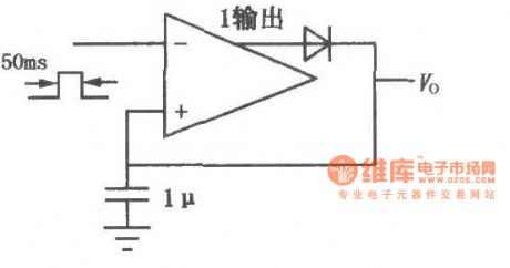
LM161/261/361 has high transmission speed, common power supply voltage, independent strobe terminal, and it has two low delay complementary TTL outputs, low input offset voltage. When the circuit is driving , the switching speed is small, and it ises double in-line package. The circuit shown as the chart is the high-speed peak detector.
(View)
View full Circuit Diagram | Comments | Reading(621)
| Pages:1715/2234 At 2017011702170317041705170617071708170917101711171217131714171517161717171817191720Under 20 |
Circuit Categories
power supply circuit
Amplifier Circuit
Basic Circuit
LED and Light Circuit
Sensor Circuit
Signal Processing
Electrical Equipment Circuit
Control Circuit
Remote Control Circuit
A/D-D/A Converter Circuit
Audio Circuit
Measuring and Test Circuit
Communication Circuit
Computer-Related Circuit
555 Circuit
Automotive Circuit
Repairing Circuit