
Circuit Diagram
Index 1707
LM161, LM1261 and LM1361--the high speed compensation voltage comparator circuit
Published:2011/6/25 4:45:00 Author:qqtang | Keyword: high speed, compensation, voltage comparator

LM161/261/361 have a high transmitting speed, a general power supply voltage, separated strobe terminals and two compensatory output TTL signals of little time delay. Its input distortion voltage is low. When it is driven, its rotating speed is low. It is in dual in-line package. In the figure is the high speed value wave detector.
(View)
View full Circuit Diagram | Comments | Reading(716)
BA3312N recording and playback processing integrated circuit
Published:2011/6/22 8:40:00 Author:Christina | Keyword: recording, playback, processing, integrated circuit

The BA3312N is designed as one kind of recording and playback processing integrated circuit that is produced by the Toyo company, it can be used in the circuits of walkmans and repeaters such as the Aiwa and the Sony series walkman.
1.Features
The BA3312N is composed of the recording and playback preamplifier circuit, the ALC signal control circuit, the voltage stabilization power supply circuit and other auxiliary circuit.
2.Pin functions and data
The BA3312N uses the 10-pin package, the pin functions and data are as shown in table 1.
Table 1 The pin functions and data of the BA3312N
(View)
View full Circuit Diagram | Comments | Reading(1509)
BA3107 fan single chip microcomputer integrated circuit
Published:2011/6/22 8:51:00 Author:Christina | Keyword: fan, single chip, microcomputer, integrated circuit


The BA3107 is designed as one kind of fan single chip microcomputer integrated circuit which is produced by the Toyo company, and it can be used in all kinds of fan control program circuits. The BA3107 uses the 22-pin dual-row DIP package, the typical application circuit is as shown in figure 1, the pin functions and data are as shown in table 1.
Figure 1 The typical application circuit of the BA3107
Table 1 The pin functions and data of the BA3107
(View)
View full Circuit Diagram | Comments | Reading(836)
SN55451B and SN75451B--the dual perpheral forward AND driver circuit
Published:2011/6/25 5:03:00 Author:qqtang | Keyword: dual, perpheral, forward driver

SN55451B/75451B is theAND logic periphery driver whose input terminal is compatible with TTL or DTL, its input current is 300mA, its input voltage is high, and its rotating speed is high. Its typical application circuit is shown in the figure.
(View)
View full Circuit Diagram | Comments | Reading(660)
The plate shape chloride steel humidity sensitive resistor circuit
Published:2011/6/22 9:28:00 Author:Christina | Keyword: plate shape, chloride steel, humidity sensitive, resistor

The plate shape chloride steel humidity sensitive resistor circuit is as shown in the figure. You can dip the Lithium chloride solution on the non-alkali glass ribbon to form the humidity sensitive component. The platinum electrode is inosculated with the glass ribbon by the pressure production method, and it is led out by the welding wire.
(View)
View full Circuit Diagram | Comments | Reading(1013)
The Mitsubishi auto escalator control circuit
Published:2011/6/25 4:55:00 Author:qqtang | Keyword: Mitsubishi, auto escalator

The Mitsubishi auto escalator control circuit is shown in the figure.
(View)
View full Circuit Diagram | Comments | Reading(3571)
The Mitsubishi auto escalator secure loop circuit
Published:2011/6/25 4:57:00 Author:qqtang | Keyword: Mitsubishi, auto escalator

The Mitsubishi auto escalator secure loop circuit is shown in the figure.
(View)
View full Circuit Diagram | Comments | Reading(1376)
The dual periphery forward OR driver circuit
Published:2011/6/25 5:02:00 Author:qqtang | Keyword: dual periphery, forward, OR driver

SN55453B/75453B is the OR logic periphery driver whose input terminal is compatible with TTL or DTL, its input current is 300mA, its input voltage is high, and its rotating speed is high. Its typical application circuit is shown in the figure.
(View)
View full Circuit Diagram | Comments | Reading(644)
BA3105 fan single chip microcomputer integrated circuit
Published:2011/6/23 6:35:00 Author:Christina | Keyword: fan, single chip, microcomputer, integrated circuit


The BA3105 is designed as one kind of fan single chip microcomputer integrated circuit which is produced by the Toyo company, and it can be used in all kinds of fan control program circuits. The BA3105 uses the 18-pin dual-row DIP package, the typical application circuit is as shown infigure 1, the pin functions and data are as shown intable1.
Table 1 The pin functions and data of the BA3105
Figure 1 The typical application circuit of the BA3105
(View)
View full Circuit Diagram | Comments | Reading(633)
SN55452B and SN75452B--The dual periphery forward NOR driver circuit
Published:2011/6/25 5:06:00 Author:qqtang | Keyword: dual periphery, forward, NOR driver

75452B/SN55452Bis the NOR logic periphery driver whose input terminal is compatible with TTL or DTL, its input current is 300mA, its input voltage is high, and its rotating speed is high. Its typical application circuit is shown in the figure.
(View)
View full Circuit Diagram | Comments | Reading(620)
The fan single chip microcomputer integrated circuit
Published:2011/6/23 6:37:00 Author:Christina | Keyword: fan, single chip, microcomputer, integrated circuit


The BA3102 is designed as one kind of fan single chip microcomputer integrated circuit which is produced by the Toyo company, and it can be used in all kinds of fan control program circuits. The BA3102 uses the 18-pin dual-row DIP package, the typical application circuit is as shown in figure 1, the pin functions and data are as shown in table 1.
Table 1 The pin functions and data of the BA3102
Figure 1 The typical application circuit of the BA3102
(View)
View full Circuit Diagram | Comments | Reading(592)
The dual-channel video amplifier circuit
Published:2011/6/25 5:08:00 Author:qqtang | Keyword: dual-channel, video amplifier

The dual-channel video amplifier circuit is shown as above.
(View)
View full Circuit Diagram | Comments | Reading(865)
TDA6120Q--the video output amplifier circuit
Published:2011/6/25 5:18:00 Author:qqtang | Keyword: video, output amplifier

TDA6120Q is a single video output amplifier of 32MHz and 125VP-P, which is in plastic DIL and curve SIL power package, its high voltage DMOS technology can drive the passive pole of the color CRT, it can be used in high definition TVs or monitors. TDA6120Q has the fast passive pole test output of the dark current circuit, when output signal is 60v (peak value), the small signal wide band is 47MHz(typical value). TDA6120Q has a high power PSRR, whose maximum gain is over 46dB. The pin arrangement and functions of TDA6120Q are shown in the figure.
(View)
View full Circuit Diagram | Comments | Reading(719)
ZhongHua saloon car engine circuit 2
Published:2011/6/19 8:52:00 Author:TaoXi | Keyword: ZhongHua, saloon car, engine
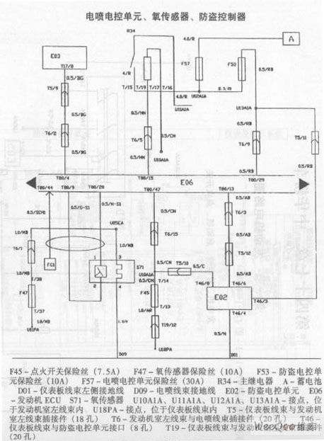
ZhongHua saloon car engine circuit (View)
View full Circuit Diagram | Comments | Reading(478)
ShangHai General WuLing car vehicle electrical system circuit 2
Published:2011/6/19 8:48:00 Author:TaoXi | Keyword: ShangHai, General, WuLing, car, vehicle electrical system
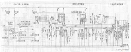
ShangHai General WuLing car vehicle electrical system circuit (View)
View full Circuit Diagram | Comments | Reading(518)
Automatic transceiver & conversion RS-485 interface circuit and testing circuit
Published:2011/6/19 8:37:00 Author:TaoXi | Keyword: Automatic transceiver, conversion, interface circuit , testing circuit


The interface circuit is as shown in the dotted line box of the figure 1, by analysising the true value table, the sending and receiving process are: when the sending port DI=O, the DE/RE=1 sends the 0 electrical level, the receiving port RO=O; when the sending port DI=1, DE/RE=0, VA=VB=2.5V, the receiving port RO=1 with the function of the pull-up resistor.
If you add the 1kHz TTL square wave at the TXo port of the interface circuit to test the circuit. The interface chip pin 485-A and pin 485-B all have the 50μs voltage changing process when you have not add the 120Ω port resistance, as the figure 2 shows. The receiving port Ro waveform's rising edge has the 30~40μs obvious delay to cause the large transmission error; when you add the 120Ω port resistance, the delay decreases, it is about 3μs.
(View)
View full Circuit Diagram | Comments | Reading(1075)
The time delay circuit of dual-way transistors
Published:2011/6/25 5:25:00 Author:qqtang | Keyword: time delay circuit, dual-way transistors
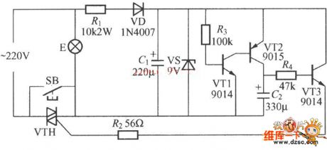
In the figure is the time delay circuit of dual-way transistors. Apart from the values of C1, C2 and R4, the timing is also relevant to the time of pressing the key. VTH can be the dual-way transistors of MAC94A4 and MAC97A6, and the β values of both VT1 and VT2 should be larger than 200.
(View)
View full Circuit Diagram | Comments | Reading(1137)
Single-chip microcomputer and LCD monitor button interface circuit
Published:2011/6/19 8:13:00 Author:TaoXi | Keyword: Single-chip microcomputer, LCD monitor, button interface

The interface circuit part of the single-chip microcomputer and the clock chip DS1302: the DS1302 is designed as one kind of high performance, low power consumption clock chip which is produced by the DALLAS company, this device uses the SPI three line interface to synchronously communicate with the CPU, and it supplies the second, the minute, the hour, the day, the week, the month and the year, when the month is less than 31 days, it can automaticly adjust, also it has the function of leap year compensation. The operating voltage is 2.5 to 5.5V, the application circuit is as shown in the figure.
The interface circuit part of the single-chip microcomputer and the LCD monitor: the data interface line of the LCD monitor is connected with the P0 port of the single-chip microcomputer. The P2.0, P2.1, P2.2 can be used in the operation of the LCD screen's reading and writing. The specific circuit is as shown in the figure.
(View)
View full Circuit Diagram | Comments | Reading(1881)
The μPC1473H/HA typical application circuit
Published:2011/6/25 20:04:00 Author:qqtang | Keyword: typical, application circuit

Figure: The μPC1473H/HA typical application circuit (View)
View full Circuit Diagram | Comments | Reading(733)
The axis temperature alarm circuit
Published:2011/6/25 20:16:00 Author:qqtang | Keyword: axis, temperature alarm

In the figure is the axis temperature alarm circuit. The alarm consists of the sensing component, time-base circuit IC1(555) and relays, etc. In this circuit, the sensing element is the temperature sensing diode(QL type), which is usually fixed in the axis box and installed on the circuit board by a self-closed plug. The temperature diode QL is in parallel connection with R1, when the axis is in a normal temperature, the resistor R1 and potentiometer W1 distribute the voltage, which make the 6-pin of 555 in a LEV which is lower than 1/3VDD(=4V)and the 3-pin output a high LEV. The corresponding pulse relay (the magnet maintaining relay) MX is in the releasing state.
(View)
View full Circuit Diagram | Comments | Reading(617)
| Pages:1707/2234 At 2017011702170317041705170617071708170917101711171217131714171517161717171817191720Under 20 |
Circuit Categories
power supply circuit
Amplifier Circuit
Basic Circuit
LED and Light Circuit
Sensor Circuit
Signal Processing
Electrical Equipment Circuit
Control Circuit
Remote Control Circuit
A/D-D/A Converter Circuit
Audio Circuit
Measuring and Test Circuit
Communication Circuit
Computer-Related Circuit
555 Circuit
Automotive Circuit
Repairing Circuit