
Circuit Diagram
Index 1712
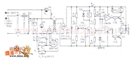
The 110~380V AC auto regulated power supply circuit
Published:2011/6/24 3:37:00 Author:Seven | Keyword: AC, power supply
View full Circuit Diagram | Comments | Reading(792)
The full-automation AC regulated power supply circuit
Published:2011/6/24 3:42:00 Author:Seven | Keyword: full-automation, power supply
View full Circuit Diagram | Comments | Reading(753)
The color TV power supply controller circuit
Published:2011/6/24 3:48:00 Author:Seven | Keyword: color TV, power supply, controller

View full Circuit Diagram | Comments | Reading(661)
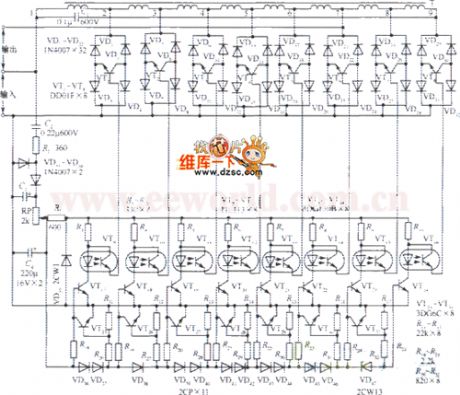
The independent power amplifier ocl circuit
Published:2011/6/24 3:50:00 Author:Seven | Keyword: power amplifier

The independent power amplifier ocl circuit is shown as above.
(View)
View full Circuit Diagram | Comments | Reading(4163)
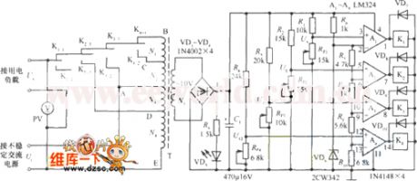
The full-automation AC regulator circuit
Published:2011/6/24 3:55:00 Author:Seven | Keyword: AC regulator, full-automation
View full Circuit Diagram | Comments | Reading(595)
The audio controlled AC regulator circuit
Published:2011/6/24 3:56:00 Author:Seven | Keyword: audio controlled, AC regulator

View full Circuit Diagram | Comments | Reading(652)
The new type color TV power supply controller circuit
Published:2011/6/24 4:02:00 Author:Seven | Keyword: new type, color TV, controller

View full Circuit Diagram | Comments | Reading(566)
The 5-12V continuous and adjustable regulated power supply circuit
Published:2011/6/24 7:10:00 Author:Seven | Keyword: regulated, power supply

View full Circuit Diagram | Comments | Reading(696)
The fridge auto deodorizer circuit
Published:2011/6/24 7:22:00 Author:Seven | Keyword: fridge, auto deodorizer
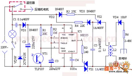
Working principles The equipment consists of the light control, time delay circuit and the passive ion generator. The equipment is controlled by the fridge internal lighting lamp. When the door is open, the lamps are on, and the LED VT1 is conducting, the 2-pin of the time-base circuit IC1 is in a low LEV immediately, the 3-pin is outputting a high LEV quickly, the dual-way controllable silicon VS is triggered and conducting, and the passive ion generator is stating to work. The working voltage of the light control and time delay control circuit is generated after the 220V AC voltage is stepped down by C1, rectified by VD1, stabilized by VDW and filtered by C2.
(View)
View full Circuit Diagram | Comments | Reading(1482)
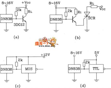
ND838 several typical application circuit
Published:2011/6/25 10:00:00 Author:John
View full Circuit Diagram | Comments | Reading(473)
Voltage stabilizer circuit outputs the positive and negative voltage simultaneously
Published:2011/6/23 8:06:00 Author:Christina | Keyword: Voltage stabilizer, positive, negative, simultaneously

Some circuits need the voltage source that can output the positive and negative voltage simultaneously, we can form the voltage stabilizer circuit that outputs the positive and negative voltage simultaneously by using the CW7800 series and CW7900 series integrated voltage stabilizers. The circuit is as shown in the figure.
Voltage stabilizer circuit outputs the positive and negative voltage simultaneously
Because this circuits use the same group of rectifier circuit, so the circuit is simple. But it is not suitable for the two-way unbalanced load circuit, otherwise it will result in the increasing of the output voltage error to destroy the stability. (View)
View full Circuit Diagram | Comments | Reading(1491)
AY-3-8600 single chip game console integrated circuit
Published:2011/6/23 8:14:00 Author:Christina
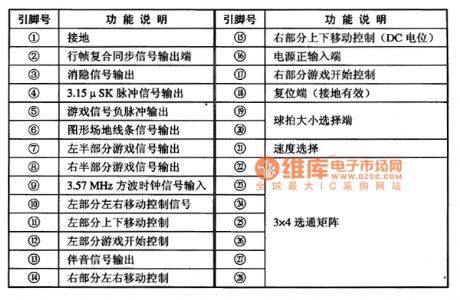

The AY-3-8600 is designed as one kind of single chip game console integrated circuit that can be used to form the toy game circuit.
1.Pin functions
The AY-3-8600 uses the 28-pin dual-row package, the pin functions are as shown in table 1. It is composed of the signal mixing circuit, the clock generator circuit and the reset circuit.etc.
Table 1 The pin functions of the AY-3-8600 integrated circuit
2.Typical application circuit
The game console typical application circuit which is composed of the AY-3-8600 integrated circuit is as shown in figure 1.
Figure 1 The typical application circuit of the AY-3-8600
(View)
View full Circuit Diagram | Comments | Reading(2559)
Boost Flyback-type single-stage isolated PFC converter circuit
Published:2011/6/25 9:40:00 Author:John | Keyword: converter

View full Circuit Diagram | Comments | Reading(1308)
ICL7135 A / D converter application circuit
Published:2011/6/25 9:38:00 Author:John | Keyword: A / D converter

View full Circuit Diagram | Comments | Reading(5256)
Three-port fixed integrated voltage stabilizer circuit
Published:2011/6/23 8:19:00 Author:Christina | Keyword: Three-port, fixed, integrated, voltage stabilizer

The 7~30V adjustable voltage stabilizer circuit which is composed of the CW7805 integrated voltage stabilizer is as shown in the figure. The F007 operational amplifier is the voltage follower, its operating voltage is directly from the DC voltage input port of the voltage stabilizer.
The 7~30V adjustable voltage stabilizer circuit (View)
View full Circuit Diagram | Comments | Reading(933)
AX5112 fan single chip microcomputer integrated circuit
Published:2011/6/24 7:12:00 Author:Christina | Keyword: fan, single chip, microcomputer, integrated circuit
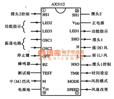
The AX5112 is designed as one kind of fan single chip microcomputer integrated circuit which is produced by the ASL company, and it can be used in various kinds of fan program control circuits.
1.Pin functions
The AX5112 uses the 20-pin dual-row DIP package, the pin functions is as shown in figure 1.
Figure 1 The pin functions of the AX5112
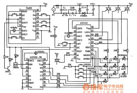
2.Typical application circuit
The remote control fan's typical application circuit which is composed of the AX5112 is as shown in figure 2.
Figure 2 The typical application circuit of the AX5112
(View)
View full Circuit Diagram | Comments | Reading(501)
Capacitive dimmer switch circuit
Published:2011/6/25 9:28:00 Author:John | Keyword: switch

Capacitive dimmer switch circuit is as shown. It uses the principle of capacitance of capacitors for AC. When the S is at the shown position, bulb E normally lights with the maximum brightness. When it is dialed to position ②, light intensity of E decreases because of the insert of 2μF capacitor C1 in series. When it is allocated to the position ③, the brightness is reduced with a block because of increasing capacitance cause by C2 <C1. And when it is allocated to the position ④, the light E is off. C1 and C2 should use non-polar oil paper capacitor which can endure more than 400V voltage. And S is the 1 × 4 single-pole four-throw switch.
(View)
View full Circuit Diagram | Comments | Reading(797)
Audi active canopy opening circuit
Published:2011/6/25 6:10:00 Author:John | Keyword: active canopy

View full Circuit Diagram | Comments | Reading(567)
Basic Boost single-stage isolated PFC converter circuit
Published:2011/6/25 6:08:00 Author:John | Keyword: converter

View full Circuit Diagram | Comments | Reading(1162)
RMS voltage detection circuit
Published:2011/6/25 6:06:00 Author:John | Keyword: voltage detection

View full Circuit Diagram | Comments | Reading(915)
| Pages:1712/2234 At 2017011702170317041705170617071708170917101711171217131714171517161717171817191720Under 20 |
Circuit Categories
power supply circuit
Amplifier Circuit
Basic Circuit
LED and Light Circuit
Sensor Circuit
Signal Processing
Electrical Equipment Circuit
Control Circuit
Remote Control Circuit
A/D-D/A Converter Circuit
Audio Circuit
Measuring and Test Circuit
Communication Circuit
Computer-Related Circuit
555 Circuit
Automotive Circuit
Repairing Circuit