
Circuit Diagram
Index 1703
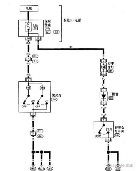
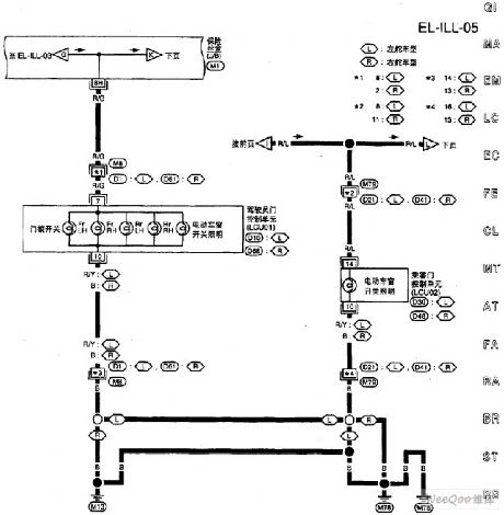
Nissan A32-EL lighting circuit 2
Published:2011/6/20 9:25:00 Author:Nancy | Keyword: Nissan, lighting circuit
View full Circuit Diagram | Comments | Reading(391)
The amplifier circuit with wide input voltage range
Published:2011/6/20 9:21:00 Author:Nancy | Keyword: wide input voltage range , amplifier circuit

The circuit shown is a wide input range amplifier composed by PGA103. The 11.3kΩ and 102kΩ resistors form the voltage division circuit, the divider ratio is about 1/10, when the input voltage is 120V, the voltage added to PGA103 input after division is only 12V, therefore wide voltage input is available. Meanwhile, didoe D1, D2(1N4148) use as two-way clamp, making the input voltage of PGA103 ±15 to 士0.7V. (View)
View full Circuit Diagram | Comments | Reading(605)
MIC4680-3.3BM application circuit
Published:2011/6/13 22:00:00 Author:Christina | Keyword: application circuit
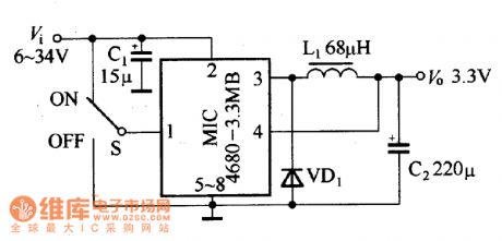
The fixed output voltage circuit which is composed of the MIC4680-3.3BM is as shown in the figure. The input voltage is 6 to 34V, the output voltage is 3.3V.
MIC4680-3.3BM application circuit (View)
View full Circuit Diagram | Comments | Reading(560)
Nissan A32-EL lighting circuit 6
Published:2011/6/20 9:24:00 Author:Nancy | Keyword: Nissan, lighting circuit
View full Circuit Diagram | Comments | Reading(424)
MAX1745 application circuit
Published:2011/6/13 22:14:00 Author:Christina | Keyword: application circuit
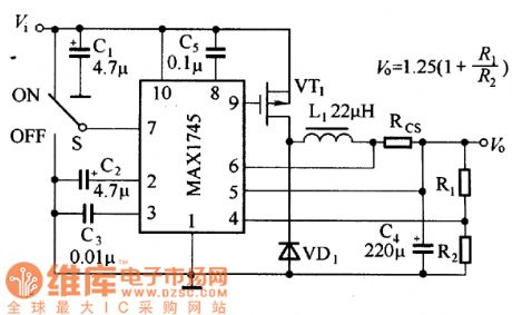
The typical application circuit of the MAXI745 is as shown in the figure, the input voltage is 5.5 to 36V, the input voltage is 1.25 to 18V, and the output voltage is decided by the partial pressure ratio of R1 and R2. The output current is decided by the current-limiting resistance RCS, and it also has relationship with the switch tube VT1 and the freewheeling diode VD1. The pin-7 of the MAX1745 can use the electrical level to close the power supply, in normal work, this pin can input the voltage Vi directly; if you want to close the power supply, you need to connect this port to ground.
MAX1745 application circuit (View)
View full Circuit Diagram | Comments | Reading(678)
Nissan A32-EL lighting circuit 5
Published:2011/6/20 9:23:00 Author:Nancy | Keyword: Nissan, lighting circuit
View full Circuit Diagram | Comments | Reading(376)
local oscillator circuit with 465KHz difference frequency
Published:2011/6/18 22:38:00 Author:Nancy | Keyword: local oscillator, 465KHz, difference frequency
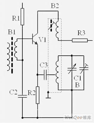
V1 is a frequency converter tube with oscillation and frequency mixing functions. The local oscillator circuit forms a transfomer feedback oscillator composed by oscillation transformer B2 and adjustable capacitor C1b, the oscillator frequency is mainly decided by L4 and C1b, the local oscillator signal is connected to V1 base-emitter though C2 and C3, the self-excited oscillation signal is coupled to oscillation loop by feedback coil and then sent back to V1 base-emitter though C3 and C2, it is amplified circularly and forms oscilltion. The input tuning signal and local oscillation signal are added to the triode simultaneously, then the sum frequency, multiplication frequency and differential frequency of two frequencies will be produced at the emitter of the triode using the non-linear characteristic of the triode. (View)
View full Circuit Diagram | Comments | Reading(914)
BA6796FP servo driving integrated circuit
Published:2011/6/13 22:22:00 Author:Christina | Keyword: servo driving, integrated circuit
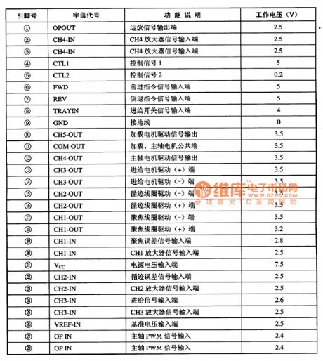
The BA6796FP is designed as one kind of servo driving integrated circuit that is produced by the Toyo company, and it can be used in the CD、VCD、SVCD、CVD、DVD.
1.Features
The BA6796FP has the 4-channel BTL driver, and it can change the laser head servo control voltage into the two-way driving voltage to drive the execution units of the servo mechanism.
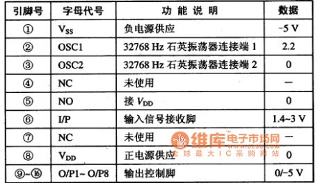
2.Pin functions and data
The BA6796FP uses the 8-pin dual-row DIP package, the pin functions and data is as shown in table 1.
Table 1 The pin functions and data of the BA6796FP
(View)
View full Circuit Diagram | Comments | Reading(449)
The transistor ionization alarm circuit
Published:2011/6/24 22:09:00 Author:qqtang | Keyword: transistor, ionization alarm

It could simplify the transistor circuit of trigger fire alarm and battery low voltage alarm by using continuous fog alarm signal but not the intermittent Beep sound alarm signal. When the impedance in the ionization room is dropping due to the fog or gas, the amplifier transistors VT1~VT3 will offer 100μA basic electrode current to the compound pipe VT4, which makes VT4 conducting and the alarm H generate sound. As the fog or gas content is higher than the regulated threshold value, the voltage limited by RP5 will push the alarm to make sounds.
(View)
View full Circuit Diagram | Comments | Reading(657)
Differential amplification basic circuit
Published:2011/6/14 1:19:00 Author:Christina | Keyword: Differential amplification, basic circuit

The differential amplification basic circuit is as shown in the figure. It is composed of two single tube amplifier circuit with the same parameters. The resistances of RB11 and RB22 are the same, they are the current-limiting resistance of the input circuit; the resistances of RB21 and RB22 are the same, they are the biasing resistor; the resistances of Rc1 and RC2 are the same, they are the collector load resistor; R is the pressure equalizing resistance of the input port, it is also the under bias resistor. The signal is input from the base electrodes of VT1 and VT2, and the signal is output from the collectors of VT1 and VT2, so this circuit has two input ports and two input ports.
The differential amplifier circuit has the high magnification to the differential mode signal, and it also has the strong inhibiting effect to the mode signal, so it solves the contradiction between the amplification and zero drift perfectly.
Figure The differential amplification basic circuit
(View)
View full Circuit Diagram | Comments | Reading(618)
MCU interface circuit
Published:2011/6/18 22:05:00 Author:Nancy | Keyword: MCU interface
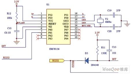
In the circuit, the L, L+ control the left motor PWM, the R, R+ control the right motor PWM. The RS232 receives coordinate data input of the sensor. IC operates at 3.3 V and resets automatically when power on. System clock uses 4MHz external crystal oscillators. (View)
View full Circuit Diagram | Comments | Reading(741)
PB5020/21/22 typical application circuit
Published:2011/6/14 1:26:00 Author:Christina | Keyword: typical application
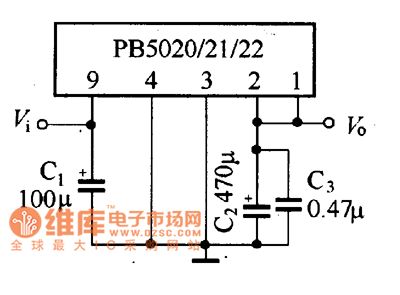
The PB5020/21/22 typical application circuit is as shown in the figure. This circuit has the features of less external components, wide input voltage range and it does not need to add the heat sink.
The MAX849 typical application circuit (View)
View full Circuit Diagram | Comments | Reading(480)
Touch screen interface circuit
Published:2011/6/18 21:58:00 Author:Nancy | Keyword: Touch screen, interface
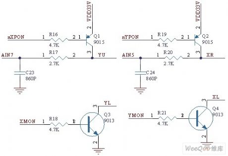
The man machine interface of vibration test analyzer uses resistance touch screen and 640×480 highlight TFT LCD, which makes the man machine interface friendly and operation simple. The S3C2410 is built with a touch screen interface circuit and the touch screen interface design is very simple. The touch screen interface circuit is shown as the figure, YU, YL, XR, XL represent the four interface signals of the resistance touch screen. (View)
View full Circuit Diagram | Comments | Reading(1402)
BA6566 call integrated circuit
Published:2011/6/14 1:31:00 Author:Christina | Keyword: call, integrated circuit


The BA6566 is designed as one kind of call integrated circuit that can be used in the Panasonic series telephone.
1.Pin functions and data
The BA6566 integrated circuit is in the 18-pin dual-row DIP package, the pin functions and data is as shown in table 1.
Table The pin functions and data of the BA6566
2.Typical application circuit
The call system typical application circuit which is composed of the BA6566 is as shown in figure 1.
Figure 1 The call system typical application circuit which is composed of the BA6566
(View)
View full Circuit Diagram | Comments | Reading(1736)
The time delay circuit composed of transistors
Published:2011/6/24 22:41:00 Author:qqtang | Keyword: time delay, transistors

In the circuit is the time delay circuit composed of transistors, which is connected with the loading after the delayed time. According to the resistance of R and the comparing voltage UE change, the delayed time can be set. In the circuit, S is the charging switch of capacitor C, when S is closed, the electricity in C is released by S, which assures of the precise delayed time next time. VD1 and VD2 are used to reduce the effect of UBE on VT1. In the circuit, the loading current can only be 50mA or so, which can be expanded by switching VT3 into the Darlington transistor.
(View)
View full Circuit Diagram | Comments | Reading(503)
BA5201 remote control decoding integrated circuit
Published:2011/6/21 0:53:00 Author:Christina | Keyword: remote control, decoding, integrated circuit
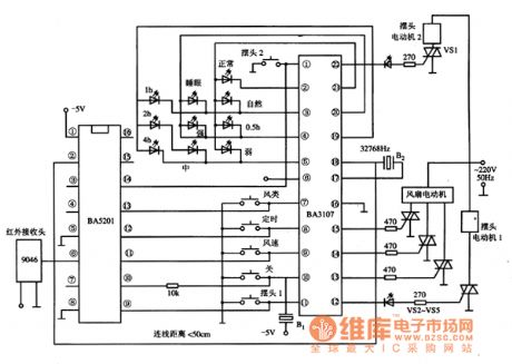
The BA5201 is designed as one kind of remote control decoding integrated circuit that is produced by the Toyo company, and it can be used in various types of remote control systems.
1.Pin functions and data
The BA5201 integrated circuit is in the 16-pin dual-row DIP package, the pin functions and data is as shown in table 1.
Table 1 The pin functions and data of the BA5201
2.Typical application circuit
The typical application circuit of the decoding system which is composed of the BA5201 is as shown in figure 1.
Figure 1 The typical application circuit of the BA5201
(View)
View full Circuit Diagram | Comments | Reading(1260)
fuse wire/filament transmitter circuit
Published:2011/6/18 21:32:00 Author:Nancy | Keyword: fuse wire, filament, transmitter

View full Circuit Diagram | Comments | Reading(959)
Magnetic induction transmitter circuit
Published:2011/6/18 21:26:00 Author:Nancy | Keyword: Magnetic induction, transmitter

View full Circuit Diagram | Comments | Reading(1140)
NISSAN new Teana navigation system circuit 8
Published:2011/6/18 21:16:00 Author:Nancy | Keyword: NISSAN, Teana navigation system

View full Circuit Diagram | Comments | Reading(638)
NISSAN new Teana navigation system circuit 11
Published:2011/6/18 21:21:00 Author:Nancy | Keyword: NISSAN, Teana navigation system

View full Circuit Diagram | Comments | Reading(732)
| Pages:1703/2234 At 2017011702170317041705170617071708170917101711171217131714171517161717171817191720Under 20 |
Circuit Categories
power supply circuit
Amplifier Circuit
Basic Circuit
LED and Light Circuit
Sensor Circuit
Signal Processing
Electrical Equipment Circuit
Control Circuit
Remote Control Circuit
A/D-D/A Converter Circuit
Audio Circuit
Measuring and Test Circuit
Communication Circuit
Computer-Related Circuit
555 Circuit
Automotive Circuit
Repairing Circuit