
Circuit Diagram
Index 1708
RCC 5V/400mA switch power supply circuit
Published:2011/6/19 8:01:00 Author:TaoXi | Keyword: RCC, 5V/400mA, switch, power supply

RCC 5V/400mA switch power supply circuit (View)
View full Circuit Diagram | Comments | Reading(3095)
HP 6L laser printer power supply circuit
Published:2011/6/19 8:00:00 Author:TaoXi | Keyword: HP, 6L, laser printer, power supply

HP 6L laser printer power supply circuit (View)
View full Circuit Diagram | Comments | Reading(8875)
ShangHai General WuLing car vehicle electrical system circuit 1
Published:2011/6/19 8:48:00 Author:TaoXi | Keyword: ShangHai, General, WuLing, car, vehicle electrical system
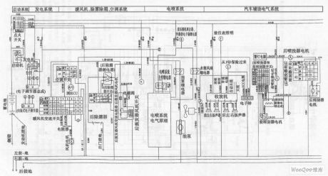
ShangHai General WuLing car vehicle electrical system circuit (View)
View full Circuit Diagram | Comments | Reading(440)
ShangHai General WuLing car united electronic & electronic control system circuit
Published:2011/6/19 8:41:00 Author:TaoXi | Keyword: ShangHai, General, WuLing car, united electronic, electronic control system
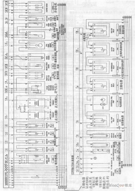
ShangHai General WuLing car united electronic & electronic control system circuit (View)
View full Circuit Diagram | Comments | Reading(386)
Switch power supply driving circuit
Published:2011/6/16 7:17:00 Author:TaoXi | Keyword: Switch, power supply, driving circuit


The driving circuit principle diagram:
The switching power supply drivingcircuit:
The main function of the driving circuit is to amplify the variable width pulse which is output by the pulse width controller, so the variable width pulse can be used as the driving signal of the high voltage power switching device. The driving circuit generally has the isolation effect, it usually uses the transformer coupling method to achieve the isolation between the high voltage power switching device's incentive input stage and incentive output stage, and it also exerts the reverse bias to accelerate the turn-off of the device. In the figure, the primary coil input signal of the driving transformer is the output driving signal of the control circuit. (View)
View full Circuit Diagram | Comments | Reading(567)
The ZhongHua saloon car air conditioning system circuit (1)
Published:2011/6/16 6:50:00 Author:TaoXi | Keyword: ZhongHua, saloon car, air conditioning, system

The ZhongHua saloon car air conditioning system circuit (1) (View)
View full Circuit Diagram | Comments | Reading(432)
KRIDENT car subwoofer circuit
Published:2011/6/19 8:02:00 Author:TaoXi | Keyword: KRIDENT, car subwoofer

KRIDENT car subwoofer circuit (View)
View full Circuit Diagram | Comments | Reading(4114)
The soft starting regulated power supply circuit
Published:2011/6/24 7:39:00 Author:Seven | Keyword: soft starting, regulated power supply

View full Circuit Diagram | Comments | Reading(662)
The dual-way thyristor dimmer circuit
Published:2011/6/24 7:53:00 Author:Seven | Keyword: thyristor, dimmer

To solve the problem the lag and jump of the light, the figured dual-way thyristor dimmer circuit of dual time constants. In the circuit, we add a R3 and C2, they are the resistance and capacitance net, the reduced electricity of C1 can be compensated in time by C2, R2 and R3, therefore, the phenomena of lag and jump can be effectively reduced, at the same time, it expands the adjusting range of the minimum brightness of the light.
(View)
View full Circuit Diagram | Comments | Reading(1040)
The EL34 power amplifier circuit
Published:2011/6/24 7:55:00 Author:Seven | Keyword: power amplifier

The EL34 power amplifier circuit is shown as above.
(View)
View full Circuit Diagram | Comments | Reading(817)
Output voltage improving circuit
Published:2011/6/23 8:56:00 Author:Christina | Keyword: Output voltage, improving


If the output voltage of the three-port fixed voltage stabilizer is lower than the needed voltage, we can use the boost circuit to improve the output voltage.The output voltage improving circuit is as shown in the figure. The R1 is connected between common ports of the output port and the voltage stabilizer, R2 is connected between common ports of the voltage stabilizer and the power supply. At this time the current of R1 is V(I1), this current gets into the R2 together with the static working current of the stabilizer. Because the static current of the stabilizer is so small (only a few mA), so when the resistance values of R1 and R2 are small, the output voltage of the circuit can be calculated from this formula:
(View)
View full Circuit Diagram | Comments | Reading(403)
Electric fan sub-ultrasonic remote control switch circuit
Published:2011/6/16 7:03:00 Author:TaoXi | Keyword: Electric fan, sub-ultrasonic, remote control, switch

The Electric fan sub-ultrasonic remote control switch circuit (View)
View full Circuit Diagram | Comments | Reading(503)
The ZhongHua saloon car ABS circuit (3)
Published:2011/6/16 6:51:00 Author:TaoXi | Keyword: ZhongHua, saloon car, ABS

The ZhongHua saloon car ABS circuit (3) (View)
View full Circuit Diagram | Comments | Reading(361)
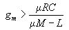
The FET crystal oscillator circuit-inductance feedback oscillator circuit
Published:2011/6/18 2:21:00 Author:Seven | Keyword: FET, crystal oscillator, inductance
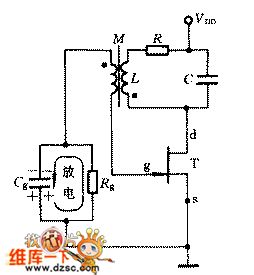
The composition of the circuit: FET T, LC parallel circuit, the fence bias voltage consisting of Rg and Cg is shown in the figure.
(1) the phase balance condition: it is judged in the instant polarity method(2) the amplitude balance condition is (View)
View full Circuit Diagram | Comments | Reading(492)
Positive and negative adjustable voltage stabilization power supply circuit
Published:2011/6/23 7:22:00 Author:Christina | Keyword: Positive, negative, adjustable, voltage stabilization, power supply

The two-way adjustable voltage stabilization power supply circuit which is composed of the CW317 and CW337 is as shown in the figure.
Positive and negative adjustable voltage stabilization power supply circuit (View)
View full Circuit Diagram | Comments | Reading(742)
The single phase full-wave rectifier circuit
Published:2011/6/17 0:53:00 Author:Seven | Keyword: single phase, full-wave rectifier


The full-wave rectifier circuit shown in the following figure consists of a transformer with 2 central heads and 2 diodes. Seeing from the circuit, we can find that both the passive and positive half periods has current run across the load, which increase the efficiency.
The features of the full-wave rectifier:The output voltage VO is high; the impulse is low; both the positive and passive half periods can provide current for the load, so the transformer is used fully, and it's efficient.The main parameters:
(View)
View full Circuit Diagram | Comments | Reading(633)
The typical application circuit of 3-terminal IC
Published:2011/6/19 3:03:00 Author:Seven | Keyword: typical application circuit, 3-terminal IC


The fixed typical application circuit of 3-terminal IC is shown in the figure. In the figure, C1 and C2 are used for frequency compensation to avoid self-oscillation and high-frequency noise; C3 is a polymer capacitor, and it can weaken the effect, which is from the low-frequency imported by the power supply, on the output voltage; D is a protection diode, when the input terminal is short, it can offer C3 a discharging circuit to stop the voltage on C3 breaking down the emitter of the regulating device.
The requirement of the 3-terminal regulated IC circuit is: (View)
View full Circuit Diagram | Comments | Reading(560)
TDA2320--(TV sets) the infrared remote control receiving pre-amplifier circuit
Published:2011/6/24 2:25:00 Author:Seven | Keyword: infrared, remote control, pre-amplifier

The TDA2320 typical application circuit (View)
View full Circuit Diagram | Comments | Reading(1707)
The auto tracking controller circuit of solar power
Published:2011/6/23 22:06:00 Author:Seven | Keyword: auto tracking controller, solar power

There are two kinds of auto tracking controllers of solar power: one is that a LDR and Schmidt trigger or a single stable trigger compose a light controlled Schmidt trigger or single stable trigger, which is to control the running/stopping of the motor; the other is that two LDR and two comparators respectively compose two light controlled comparators that control the motor. As the light and its strength change a lot in different seasons and hours, so it's hard for the above controllers to make the solar tracking equipment follow the sun.
(View)
View full Circuit Diagram | Comments | Reading(3550)
The AY-3-8500 and AY-3-8500-1 single chip game console integrated circuits
Published:2011/6/23 8:43:00 Author:Christina | Keyword: single chip, game console, integrated circuits


The AY-3-8500 and AY-3-8500-1 are designed as the single chip game console integrated circuits that can be used in the toy game circuit.
1.Features
The AY-3-8500 and AY-3-8500-1 integrated circuits are composed of the image signal generating circuit, the audio signal generating circuit, the image storage circuit, the random storage circuit, the counter, the logic control circuit, the clock oscillating circuit, the synchronous signal processing circuit and other functional circuit.
2.Pin functions and data
The AY-3-8500 and AY-3-8500-1 integrated circuits have the same functions, only a few pins have different functions, both of the AY-3-8500 and AY-3-8500-1 use the 28-pin dual-row DIP plastic encapsulation structure, the pin functions and data of the AY-3-8500 is as shown in table 1, the pin functions and data of the AY-3-8500-1 is as shown in table 2
Table 1 The pin functions and data of the AY-3-8500
Table 2 The pin functions and data of the AY-3-8500-1
(View)
View full Circuit Diagram | Comments | Reading(680)
| Pages:1708/2234 At 2017011702170317041705170617071708170917101711171217131714171517161717171817191720Under 20 |
Circuit Categories
power supply circuit
Amplifier Circuit
Basic Circuit
LED and Light Circuit
Sensor Circuit
Signal Processing
Electrical Equipment Circuit
Control Circuit
Remote Control Circuit
A/D-D/A Converter Circuit
Audio Circuit
Measuring and Test Circuit
Communication Circuit
Computer-Related Circuit
555 Circuit
Automotive Circuit
Repairing Circuit