
Circuit Diagram
Index 1713
single-stage full-bridge PFC converter circuit
Published:2011/6/25 6:04:00 Author:John | Keyword: converter

PFC technology has been gradually integrated into a lot of good converter circuits. The new developed structures can well suppress power supply to input harmonics, regulating the input current’s waveform. They also have excellent output characteristics, fully achieving the advantages of PFC circuit and power conversion circuit. The figure shows the single-stage PFC circuit formed by the Boost circuit and full-bridge converter. As for practical applications, the synthesis circuit improves the charging and discharging circuit of VDx1 and VDx2, thus leading to better functions.
(View)
View full Circuit Diagram | Comments | Reading(2335)
The merging power amplifier circuit
Published:2011/6/24 7:24:00 Author:Seven | Keyword: power amplifier

The merging power amplifier circuitis shown as above.
(View)
View full Circuit Diagram | Comments | Reading(824)
The single key digital dimmer circuit
Published:2011/6/24 8:00:00 Author:Seven | Keyword: single key, digital dimmer

The single key digital dimmer circuit is shown in the figure, which is a thyristor trigger circuit composed of the CD4017 digital circuit and the single knot thyristor. It can adjust the brightness in 10 gears, and it is very convenient to use.
(View)
View full Circuit Diagram | Comments | Reading(3233)
Audi (without DRL) external light circuit
Published:2011/6/25 5:52:00 Author:John | Keyword: external light

View full Circuit Diagram | Comments | Reading(604)
The farm thermostat controller circuit diagram
Published:2011/6/18 21:29:00 Author:Lucas | Keyword: farm, thermostat controller

The farm thermostat controller circuit is composed of the power supply circuit and temperature control circuit, and the circuit is shown in the chart. Power supply circuit is composed of the power switch S, fuse FU, power transformer T, bridge rectifier UR, filter capacitors C1, C2, and three-terminal voltage regulator integrated circuit IC. Temperature control circuit consists of electric heating thermometer Q, relay K, intermediate relay KA, AC contactor KM, electric heater EH and heating indicator light HL. C1 and C2 select the aluminum electrolytic capacitor with the voltage above 35V. UR selects the 1 ~ 2A, 50V bridge rectifier. IC selects 78H24 three-terminal regulator IC.
(View)
View full Circuit Diagram | Comments | Reading(454)
Automatic sprinkler controller circuit diagram 2
Published:2011/6/18 21:54:00 Author:Lucas | Keyword: Automatic , sprinkler controller

The automatic sprinkler controller circuit is composed of the power supply circuit, switch control circuit, astable oscillator circuit and control implementation circuit, and the circuit is shown in the chart. Power supply circuit consists of the power switch s1, power transformer T, bridge rectifier UR and filter capacitor C1. Switch control circuit consists of the humidity sensor, sampling tube VI, composite amplifier tubes V2, V3, and power filter control resistors R1 ~ R4. Astable multivibrator consists of the time-base integrated circuit IC and the external RC components. Control implementation circuit is composed of the transistor V4, LEDs VL, thyristor VT, and manual control switch S2 and so on.
(View)
View full Circuit Diagram | Comments | Reading(1146)
Preamplifier and post amplifier circuit
Published:2011/6/19 10:39:00 Author:John | Keyword: Preamplifier, post amplifier
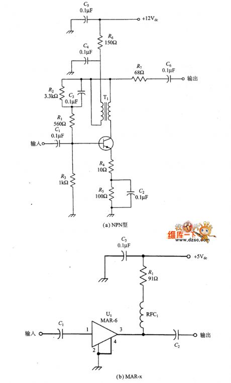
It is always justified to use an amplifier in the double-balanced mixer circuit. Pre-amp can be more sensitive to the input. When an amplifier (post amplifier) is connected into the passive double-balanced mixer output, it can compensate a loss of 5 ~ 8dB for the passive double-balanced mixer. No matter what, the amplifier can provide a certain amount of isolation for either input or output of the double balanced mixer. The impact caused by the double-balanced mixer from the source or fluctuations in load impedance can be in the liberation. In this case, the amplifier is known as a buffer amplifier.
(View)
View full Circuit Diagram | Comments | Reading(905)
Product detector circuit
Published:2011/6/19 9:17:00 Author:John | Keyword: detector

For SSB, it must be demodulated to recover the audio modulation. The circuit shown in the figure can get the job done well. It uses an LM-1496 double-balanced mixer as a product detector. This detector operates in CW, SSB and DSB signal (all of which need a local oscillator to inject signals). And audio signal can be generated by combining the local oscillator signal and the receiver’s SSB IF signal superheterodyne All of the SSB receivers use certain product detector in the end IF chain, many of which use some similar LM-1496 circuits just shown in the figure.
(View)
View full Circuit Diagram | Comments | Reading(2589)
Automatic feeding controller circuit diagram
Published:2011/6/18 21:35:00 Author:Lucas | Keyword: Automatic, feeding controller

The automatic feeding controller circuit is composed of the power supply circuit, pulse oscillator, electromagnetic control circuit and motor control circuit, and the circuit is shown in the chart. Power supply circuit is composed of the knife switch Q, fuses FU1 ~ FU3, buck capacitors C1, C2, drain resistor R1, control switch S, relay K, rectifier diode VD1, voltage regulator diode VS and filter capacitor C3. Pulse oscillator is composed of the resistor R6, potentiometers RP1, RP2, diodes VD3, VD4, capacitors C4, C12, and time-base integrated circuit IC. The electromagnetic control circuit consists of the electromagnet VA, resistors R7 ~ R9, R13, potentiometer RP3, diodes VD2, VD5, transistor V, capacitor C5 and thyristor VT1.
(View)
View full Circuit Diagram | Comments | Reading(715)
Optically controlled insects trap lamp circuit diagram
Published:2011/6/18 21:00:00 Author:Lucas | Keyword: optically controlled, insects, trap lamp

The optically controlled insects trap lamp circuit is composed of the bidirectional diode thyristor VT, two-way trigger diode V, photoresistor RC, resistor R, capacitor C, and light bulb EL, and the circuit is shown in the chart. R selects the 1W metal film resistor. RC uses MC45 series of photosensitive resistor, and it should be applied with a transparent rain cover. C selects the polyester capacitor or CBB capacitor with the voltage in 400V. V uses the DB3 or 2CTS2 two-way trigger diode. VT uses TLC336A (3A, 600V) bidirectional diode thyristor. EL uses 5 to 10 pieces of 40W, 220V incandescent bulbs conected in parallel, and the installation should add rain-proof glass shade, and lamp shade should be brushed a layer of black lacquer to enhance the effect of attracting insects.
(View)
View full Circuit Diagram | Comments | Reading(1263)
Matching circuit and signal receiving circuit diagram
Published:2011/6/20 6:26:00 Author:Lucas | Keyword: Matching circuit , signal receiving

Internal receiver circuit works rely on the responding signals of card having modulation function on the bilateral area of sub-carrier. VMID signal produced by the internal circuit of MFRC522 is used as the bias of RX pin input signal. It needs to connect a capacitor C4 between VMID and GND for stabilizing VMID output. Receiver circuit needs to be connected a voltage divider circuit between the RX and VMID. The matching circuit and the signal receiving circuit is shown as the chart. The figure includes EMC low pass filter (L01, L02, C01, C02), receiver circuit (R66, C3, R65, C4), antenna matching circuit (C03, C04 , C2A, C2B, R2A, R2B) and antenna.
(View)
View full Circuit Diagram | Comments | Reading(2098)
The chicken farm temperature controller circuit diagram
Published:2011/6/18 21:45:00 Author:Lucas | Keyword: chicken farm, temperature controller

The chicken farm temperature controller circuit consists of temperature detection circuit, temperature control circuit and temperature analog display circuit, and the circuit is shown in the chart. Temperature detection circuit is composed of the integrated temperature sensor IC1, and the the N3, N4 which are inside of operational amplifier integrated circuits IC2 (N1, N2), IC3 (N3 ~ N5), resistors R1 ~ R10 and potentiometer RP1. Temperature control circuit is composed of the N5 which is inside of IC3, diodes VD1, VD2, dual time-base integrated circuit IC4, resistors R12 ~ R15, light emitting diodes VL11, VL12, potentiometer RP2 and relay Κ. Temperature analog display circuit consists of the LED display driver IC IC5, control switch S, resistor R11, potentiometer RP3 and light-emitting diodes VL1 ~ VL10. R1 ~ R15 select the 1/4W carbon film resistors or metal film resistors.
(View)
View full Circuit Diagram | Comments | Reading(1780)
The barton automatic controller circuit diagram
Published:2011/6/18 22:57:00 Author:Lucas | Keyword: barton , automatic controller

The automatic control circuit is composed of the power supply circuit, humidity detection control circuit, light detection control circuit and temperature detection control circuit, and the circuit is shown in Figure 38. Power supply circuit is composed of the power transformer T, bridge rectifier UR1, LED HL, three-terminal integrated regulator IC and filter capacitor C1. Humidity humidity detection control circuit consists of resistor RS, bridge rectifier UR2, potentiometer RP1, transistors V1, V2, diodes VD1, VD2, resistors R1 ~ R4, capacitor C2 and relay K1. Light detection control consists of the photosensitive transistor V3, transistors V4, V5, resistors R5 ~ R8, potentiometer RP2, diodes VD3, VD4, and relay K2. Temperature detection circuit is composed of the thermistor control circuit RT, resistors R9 ~ R12, transistors V6, V7, capacitor C4, potentiometer RP3, diodes VD5, VD6 and relay K3.
(View)
View full Circuit Diagram | Comments | Reading(506)
mixer based on LM-1496 circuit
Published:2011/6/19 7:40:00 Author:John | Keyword: mixer

The picture shows the basic LM-1496 mixer circuit. In the figure, RF and carrier input are connected together to form a single-ended structure. Respective signals are sent from the input end through the DC blocking capacitors C1 and C2. Respective pin is connected to the ground through capacitors C3 and C4. Broadband output network includes a 9:1 RF transformer. The two outputs are combined together and their impedance is down to 50Ω. Transformer primary coil resonates the IF frequency through C5.
figure: mixer based on LM-1496 circuit (View)
View full Circuit Diagram | Comments | Reading(1991)
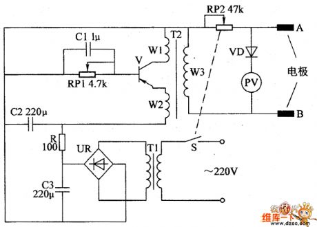
Biological taking poison device circuit diagram 3
Published:2011/6/18 22:50:00 Author:Lucas | Keyword: Biological , taking poison device
The biological taking poison device circuit is composed of the power supply circuit, multivibrator and output circuit, and the circuit is shown in Figure 37. Power supply circuit consists of the power switch S, battery GB, current limiting resistor R1 and the power indicator light-emitting diode VL. Multivibrator is composed of the capacitors C1, C2, resistor R2, potentiometer RP1 and time-base integrated circuit IC. Output circuit is composed of the pulse transformer T, potentiometer RP2, voltmeter N and electrodes A, B. R1 and R2 use the l/4W carbon film resistors or metal film resistors. RP1 uses the WH series of small synthetic membrane switch potentiometer without switch; RP2 uses the WH series of small synthetic carbon film potentiometer with switch.
(View)
View full Circuit Diagram | Comments | Reading(477)
Double-balanced diode mixer circuit
Published:2011/6/19 7:20:00 Author:John | Keyword: diode

The circuit uses a ring diode mixer with balanced input, output and LO ports. It can achieve isolation between ports of 30 ~ 60dB. In the actual circuit, characteristics are also very good. Double-balanced mixer shown in the figure is widely used in a variety of designs by electronics enthusiasts and amateur radio enthusiasts. Such designs are the direct conversion receiver, single-sideband transmitter and high-performance short-wave receiver. If it is designed well, just a double-balanced mixer can work within a very wide frequency range.
(View)
View full Circuit Diagram | Comments | Reading(943)
Biological taking poison device circuit diagram 2
Published:2011/6/18 22:45:00 Author:Lucas | Keyword: Biological , taking poison device
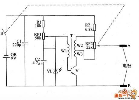
The biological taking poison device circuit is actually low-frequency oscillator circuit which is composed of the transistor V, pulse transformer T and the realted external components, and the circuit is shown in the chart. Adjusting the resistance of RP1 can change the working frequency of low-frequency oscillator. Regulation the resistance of RP2 can change the output pulse voltage amplitude (ie, the intensity of electrical pulses). R1 and R2 select 1/4W gold film resistors. RPI uses WH-15 series of small synthetic membrane potentiometer without switch; RP2 uses WH-15 series of small synthetic carbon film potentiometer with switch. C1 and C2 select the aluminum electrolytic capacitor with the voltage in 16V. VL chooses Φ3mm red light-emitting diode.
(View)
View full Circuit Diagram | Comments | Reading(408)
Duplex filter electric appliance circuit
Published:2011/6/19 7:13:00 Author:John | Keyword: Duplex filter, electric appliance

There are two tasks for duplex filter: ① to absorb unwanted mixer output signals so that they do not reflect back to the mixer; ② to send wanted signals to the output. In the figure, these two functions are achieved by two different LC networks. One is a high-pass filter and the other one is a low-pass filter. The assumption differential frequency signals in the circuit is what we need, so a high-pass filter (it’s half-power’s frequency is higher than the differential frequency) is used to guide frequency signals (that refers to the signal combination of RF and LC in the mixing process) to effective load R1. (View)
View full Circuit Diagram | Comments | Reading(734)
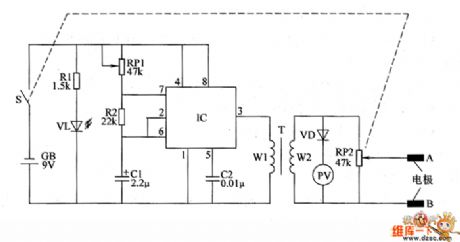
Biological taking poison device circuit diagram 1
Published:2011/6/18 22:39:00 Author:Lucas | Keyword: Biological, taking poison device
Biological taking poison device circuit is composed of the power supply circuit, self-excited intermittent oscillator and output circuit, and the circuit is shown in the chart. Power supply circuit is composed of the power switch S, power transformer T1, bridge rectifier UR, filter capacitors C2, C3 and current limiting resistor R. Self-excited intermittent oscillator is composed of the capacitor C1, potentiometer RP1, transistor V, the windings W1, W2 of pulse transformer T2. Output circuit is composed of the winding W3 of pulse transformer T2, potentiometer RP2, diodes VD, voltmeter PV and electrodes A, B. Adjusting the RP1 resistance can change the frequency of self-excited intermittent oscillator.
(View)
View full Circuit Diagram | Comments | Reading(472)
The electric fence control circuit diagram 9
Published:2011/6/18 22:27:00 Author:Lucas | Keyword: electric fence , control

The electric fence control circuit is composed of the power supply circuit, trigger control circuit, high voltage circuit and alarm circuit, and the circuit is shown in the chart. Power supply circuit is composed of the power switch S1, voltmeter PV, fuse FU, resistors R1, R9, power indicators HL1, HL2, power transformer T1, bridge rectifiers UR1 ~ UR3, capacitors C1, C5, C8, inductor L, ammeter PA, diode VD4 and regulator diode VS. Trigger control circuit is composed of the capacitor C9, potentiometer RP1, resistors R10, R11, single-junction transistor VU, isolation transformer T3 and diode VD6. The high-voltage circuit is composed of diode VD5, thyristor VT2, resistors R7, R8, capacitors C6, C7, neon light HL2 and high-voltage transformer T2.
(View)
View full Circuit Diagram | Comments | Reading(1852)
| Pages:1713/2234 At 2017011702170317041705170617071708170917101711171217131714171517161717171817191720Under 20 |
Circuit Categories
power supply circuit
Amplifier Circuit
Basic Circuit
LED and Light Circuit
Sensor Circuit
Signal Processing
Electrical Equipment Circuit
Control Circuit
Remote Control Circuit
A/D-D/A Converter Circuit
Audio Circuit
Measuring and Test Circuit
Communication Circuit
Computer-Related Circuit
555 Circuit
Automotive Circuit
Repairing Circuit