
Circuit Diagram
Index 1720
The oscillating frequency mixer circuit
Published:2011/6/19 20:21:00 Author:qqtang | Keyword: oscillating frequency
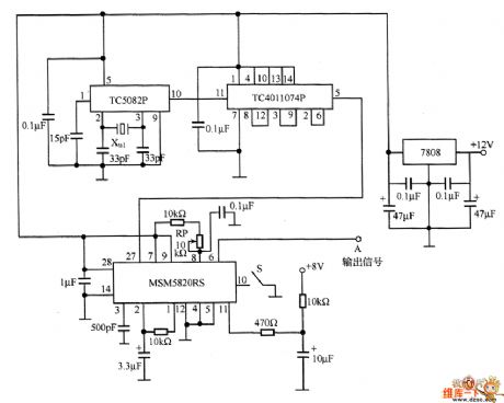
When the required frequency stabilization is high, the oscillator is often made of crystal, because the crystal temperature character is very high. In fact, we often need the improved high-stabilization oscillating circuit, that's why we need to fine-tune the oscillating frequency, and the temperature character is the same when the frequency reaches some values. It's not enough to choose the crystal, therefore, we can use phase-lock PLL frequency mixer. See as the figure, this is the frequency mixer, the chip of the mixer is MSM5820RS.
(View)
View full Circuit Diagram | Comments | Reading(649)
Mazda 95TAURUS (3.8L) analog instrument panel circuit
Published:2011/6/21 0:37:00 Author:John | Keyword: analog instrument panel

Mazda 95TAURUS (3.8L) analog instrument panel circuit is shown.
(View)
View full Circuit Diagram | Comments | Reading(552)
Mazda 95TAURUS (3.0L) lamp monitor circuit
Published:2011/6/21 0:37:00 Author:John | Keyword: lamp monitor

Mazda 95TAURUS (3.0L) lamp monitor circuit is shown.
(View)
View full Circuit Diagram | Comments | Reading(597)
Mazda 95TAURUS (3.0L, SHO) charging system circuit
Published:2011/6/21 0:37:00 Author:John | Keyword: charging system
Mazda 95TAURUS (3.0L, SHO) charging system circuit is shown.
(View)
View full Circuit Diagram | Comments | Reading(455)
The sine wave output circuit
Published:2011/6/23 20:09:00 Author:Seven | Keyword: sine wave, output
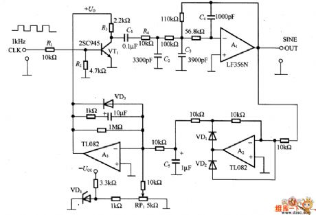
In the circuit, VT1 is the AM circuit, it switches the control voltage +UG with a 1KHz clock signal and generates square wave, then the high frequency harmonic wave is filtered by the low-pass filter. R4 and C2 are used to set the flat time constant of the wave front edge, A1 is the buffer amplifier. The half-wave output by A1 is rectified by the ideal diode which is composed by A2, and C5 smooths the rectifier output, and the output is compared with the VD4 reference voltage, if it is higher than the Vref, then the output of A3 is dropping and UG on VT1 is falling.
(View)
View full Circuit Diagram | Comments | Reading(712)
Mazda 95TAURUS (3.0L, SHO) engine performance circuit
Published:2011/6/21 0:37:00 Author:John | Keyword: engine performance

Mazda 95TAURUS (3.0L, SHO) engine performance circuit is shown.
(View)
View full Circuit Diagram | Comments | Reading(715)
Mazda 95TAURUS (3.0L, SHO) transmission circuit
Published:2011/6/21 0:37:00 Author:John | Keyword: transmission

Mazda 95TAURUS (3.0L, SHO) transmission circuit is shown.
(View)
View full Circuit Diagram | Comments | Reading(555)
Mazda 95TAURUS (3.2L, SHO) charging system circuit
Published:2011/6/21 0:38:00 Author:John | Keyword: charging system

Mazda 95TAURUS (3.2L, SHO) charging system circuit is shown.
(View)
View full Circuit Diagram | Comments | Reading(563)
Mazda 95TAURUS (3.2L, SHO) engine performance circuit
Published:2011/6/21 0:38:00 Author:John | Keyword: engine performance

Mazda 95TAURUS (3.2L, SHO) engine performance circuit is shown.
(View)
View full Circuit Diagram | Comments | Reading(586)
Mazda 95TAURUS (3.2L, SHO) transmission circuit
Published:2011/6/21 0:38:00 Author:John | Keyword: transmission

Mazda 95TAURUS (3.2L, SHO) transmission circuit is shown.
(View)
View full Circuit Diagram | Comments | Reading(592)
Mazda 95TAURUS (3.8L) ABS circuit
Published:2011/6/21 0:38:00 Author:John | Keyword: ABS

Mazda 95TAURUS (3.8L) ABS circuit is shown.
(View)
View full Circuit Diagram | Comments | Reading(630)
Mazda 95TAURUS (3.8L) charging system circuit
Published:2011/6/21 0:38:00 Author:John | Keyword: charging system

Mazda 95TAURUS (3.8L) charging system circuit is shown.
(View)
View full Circuit Diagram | Comments | Reading(570)
Mazda 95TAURUS (3.8L) electronic instrument panel circuit
Published:2011/6/21 0:39:00 Author:John | Keyword: electronic instrument panel

Mazda 95TAURUS (3.8L) electronic instrument panel circuit is shown.
(View)
View full Circuit Diagram | Comments | Reading(574)
An air-conditioner mainboard circuit
Published:2011/6/19 20:35:00 Author:qqtang | Keyword: air-conditioner, mainboard

View full Circuit Diagram | Comments | Reading(867)
The ladder wave signal generating circuit
Published:2011/6/23 20:50:00 Author:Seven | Keyword: ladder wave, signal generating

In the figure is the ladder wave signal generating circuit. In the circuit, 74HC193 is a 4-bit binary counter, on the output terminal connects with a R-2R resistor ladder net, which composes a 4-bit D/A converter. The 15th stage voltage is the total value of all the 5V power supply, i.e 5V×15/16=4.6875V, the voltage on each stage is 312.5mV. To make the maximum voltage 10V, A1 magnifies it to its twice, if the voltage on each stage is not suitable in usage, the voltage can be split on its output terminal.
(View)
View full Circuit Diagram | Comments | Reading(1142)
The simple ring choking switch regulated power supply circuit
Published:2011/6/23 10:35:00 Author:qqtang | Keyword: choking, regulated power supply

The simple ring choking switch regulated power supply circuit is shown as above.
(View)
View full Circuit Diagram | Comments | Reading(683)
The timing circuit composed of TC9160
Published:2011/6/23 1:31:00 Author:qqtang | Keyword: timing circuit

In the figure is the timing circuit composed of TC9160. Generally, a timing circuit discharges with capacitors, as the charge/discharge is not in linearity, so the time is not the evenly spaced scale. Besides, if we want to acquire a timing over 10 min, we need capacitors of more than 1000μF and resistors of several hundred MΩ. Though the NE555 timer circuit is simple, but it needs capacitors of little leakage and large insulated resistance.
TC9160 is an integrated circuit contains frequency splitting counters, its working voltage is low, which is 1.8v. Its consuming current is low. (View)
View full Circuit Diagram | Comments | Reading(847)
The flash mode connection circuit
Published:2011/6/19 20:36:00 Author:qqtang | Keyword: flash mode, connection

The flash mode connection circuit is shown in the figure.
(View)
View full Circuit Diagram | Comments | Reading(496)
The reversal switch power supply circuit
Published:2011/6/21 21:46:00 Author:qqtang | Keyword: reversal switch, power supply circuit

The typical circuit of the reversal switch power supply is shown in the figure. This kind of circuit is also called the step-up/down switch power supply. No matter whether the impulse DC voltage before TV1 is higher or lower than the output terminal stable voltage, the circuit can still work.
When VT1 is conducting, the inductance L is storing energy, the diode VD1 is blocked, the load RL is powered by the electricity in the capacitor C. When the switch VT1 is blocked, the inductance L is still conducting and inducting a voltage whose upper part is passive and lower part is positive, and it provides with power for the load with the help of diode VD1. (View)
View full Circuit Diagram | Comments | Reading(515)
The short pulse string waveform generating circuit
Published:2011/6/23 20:26:00 Author:Seven | Keyword: short, pulse string, waveform
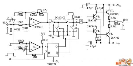
In the figure is the short pulse bundle waveform generating circuit.
A2 is the comparator, which detect the positive zero crossing point, and it outputs short pulse wave strings from sin0°, and the wave string is synchronized by 74HC74. The output time of the short pulse string is provided by the external pulse generator, but this will make it not synchronize with the phase of the sine wave oscillator, so when it reaches the high LEV with the help of the short control pulse, it makes the Q point of the dual stable state multi-resonance oscillator 74HC74 in a high LEV, then analog switch DG201CJ is on and the pulse string is output by the buffer. (View)
View full Circuit Diagram | Comments | Reading(547)
| Pages:1720/2234 At 2017011702170317041705170617071708170917101711171217131714171517161717171817191720Under 20 |
Circuit Categories
power supply circuit
Amplifier Circuit
Basic Circuit
LED and Light Circuit
Sensor Circuit
Signal Processing
Electrical Equipment Circuit
Control Circuit
Remote Control Circuit
A/D-D/A Converter Circuit
Audio Circuit
Measuring and Test Circuit
Communication Circuit
Computer-Related Circuit
555 Circuit
Automotive Circuit
Repairing Circuit