
Circuit Diagram
Index 1709
BA3106 fan single chip microcomputer integrated circuit
Published:2011/6/22 9:07:00 Author:Christina | Keyword: fan, single chip, microcomputer, integrated circuit


The BA3106 is designed as one kind of fan single chip microcomputer integrated circuit which is produced by the Toyo company, and it can be used in all kinds of fan control program circuits. The BA3106 uses the 22-pin dual-row DIP package, the typical application circuit is as shown in figure 1, the pin functions and data are as shown in table 1.
Figure 1 The typical application circuit of the BA3106
Table 1 The pin functions and data of the BA3106
(View)
View full Circuit Diagram | Comments | Reading(555)
Switch integrated voltage-stabilizing circuit
Published:2011/6/21 1:21:00 Author:Christina | Keyword: Switch, integrated voltage-stabilizing


The model numbers and features of some switch integrated voltage-stabilizing circuits are as shown in the table .
(View)
View full Circuit Diagram | Comments | Reading(472)
ELM95 series application circuit
Published:2011/6/14 2:13:00 Author:Christina | Keyword: application circuit

The ELM95 series DC/DC convertor application circuit is as shown in the figure. This circuit has very few external components, it only has the inductor, the diode and the capacitor.
The ELM95 series DC/DC convertor application circuit
In application you should pay attention to choose the small inductance coil resistance and it can not appear the magnetic saturation, the diode need to have the fast switching speed, the pressurization of the capacitor is at least 3 times of the output voltage. (View)
View full Circuit Diagram | Comments | Reading(498)
BA6430S motor driving integrated circuit
Published:2011/6/14 1:46:00 Author:Christina | Keyword: motor driving, integrated circuit


The BA6430S is designed as one kind of motor driving integrated circuit that is produced by the Toyo electric tool company, and this device can be used in the DVD players and DVs such as the Panasonic NV一M800 DV.
1.Features
The BA6430S has the torque control circuit, the position signal processing circuit, the differential amplifier circuit, the universal control circuit, the motor driver circuit and other subsidiary circuits. The internal circuit block diagram is as shown in figure 1.
2.Pin functions and data
The BA6430S uses the 24-pin dual-row DIP package, the pin functions and data is as shown in table 1.
Figure 1 The internal circuit block diagram and the typical application circuit of the BA6430S
Table 1 The pin functions and data of the BA6430S
3.The typical application circuit
The typical application circuit of the BA6430S is as shown in figure 1
Tip: The input torque control voltage (2.5V) of the BA6430S's pin-16 is the key point of this IC. (View)
View full Circuit Diagram | Comments | Reading(1383)
MAX849 application circuit
Published:2011/6/14 1:35:00 Author:Christina | Keyword: application circuit

The MAX849 application circuit is as shown in the figure. This application circuit has the fixed output voltage of 3.3V, and the output current is 200mA.
MAX849 application circuit (View)
View full Circuit Diagram | Comments | Reading(517)
BA5406 dual-channel audio power amplifier integrated circuit
Published:2011/6/14 2:33:00 Author:Christina | Keyword: dual-channel, audio, power amplifier, integrated circuit


The BA5406 is designed as one kind of dual-channel audio power amplifier integrated circuit that is produced by the Toyo electric tools company, and it can be used in variety kinds of sound systems as the audio power amplifier, such as the home audio, computer audio, car audio.etc.
1.Features
The BA5406 is composed of two groups of audio power amplifier circuit with the same functions, it has the features of good low voltage characteristics, wide power supply voltage range (4.5V-15V), high frequency phase compensation and symmetrical two-channel derivation pin. The internal circuit block diagram is as shown in figure 1.
Figure 1 The internal circuit block diagram of the BA5406
2.Pin functions and data
The BA5406 uses the 12-pin single-row DIP package, the pin functions and data are as shown in table 1.
Table 1 The pin functions and data of the BA5406
3.Typical application circuit
The typical application circuit of the BA5406 dual-channel audio power amplifier integrated circuit is as shown in figure 1.
Figure 1 The typical application circuit of the BA5406
(View)
View full Circuit Diagram | Comments | Reading(6618)
The FSK signal demodulation circuit composed of the digital phase-lock
Published:2011/6/24 2:38:00 Author:Seven | Keyword: FSK, signal demodulation, phase-lock
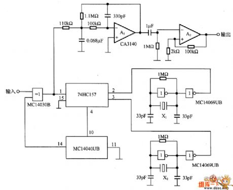
In Figure 7-2 is the FSK signal demodulation circuit composed of the digital phase-lock. The circuit consists of 2 oscillators with different frequencies, i.e crystal oscillators X (the frequency is 983.04KHz) and X2 (the frequency is 1.2288MHz) compose the oscillator, and X2 consists of the frequency converting circuit 74HC157, frequency splitting circuit MC14040B, phase comparator MCI4030B and so on. The output signal of the comparator MC14030B is delivered into the converting circuit 74HC157, by adjusting the ratio of frequency 1 and frequency 2, the output frequency can be any one between the two frequencies.
(View)
View full Circuit Diagram | Comments | Reading(2841)
The 1200Hz~100kHz clock signal source circuit
Published:2011/6/24 3:14:00 Author:Seven | Keyword: 1200Hz~100kHz, clock signal source
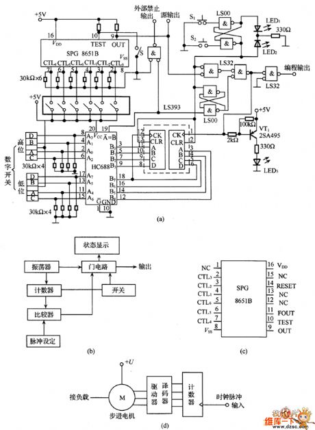
In figure 6-39 is the 1200Hz~100kHz clock signal source circuit, of which figure (b) is the circuit frame circuit, see from the frame circuit, we know that the counter counts the output pulse of the oscillator, and then the pulse is compared with the digital switch set value by the comparator, if the pulse reaches the set value, the gate circuit will be closed and the pulse is prevented from inputting. Figure (a) is the clock signal source circuit, in the circuit, the oscillator is the standard clock pulse generator SPG8651B, in the chip is the crystal oscillator circuit, the pin arrangement is shown in figure (c).
(View)
View full Circuit Diagram | Comments | Reading(1072)
Low voltage DC converter circuit
Published:2011/6/21 1:05:00 Author:Christina | Keyword: Low voltage, DC, converter

The low voltage DC converter circuit which is composed of the CW1524 is as shown in the figure. The secondary winding of the high frequency transformer T can be set according to the output voltage, the secondary winding of the figure has two groups of output: +15V and -15V.
The low voltage DC converter circuit which is composed of the CW1524 (View)
View full Circuit Diagram | Comments | Reading(723)
MAX761 application circuit
Published:2011/6/14 2:21:00 Author:Christina | Keyword: application circuit

The MAX761 typical application circuit is as shown in the figure. The output voltage Vo of this circuit depends on the connection method of pin-3, if pin-3 is connected with the ground, you need to choose the internal feedback control of the IC, the output voltage is 12V; when the pin-3 is connected with R1 and R2, you need to choose the outside feedback control, at this time the output voltage is decided by the formula: Vo=1.5(R1+R2)/R2.
By adjusting the resistance value of R1 and R2, you can get different output voltage.
MAX761 application circuit
(View)
View full Circuit Diagram | Comments | Reading(541)
The 6DJ8+6AS7(6080) high current headphone amplifier circuit
Published:2011/6/23 22:10:00 Author:Seven | Keyword: high current, headphone amplifier

The 6DJ8+6AS7(6080) high current headphone amplifier circuit is shown as above.
(View)
View full Circuit Diagram | Comments | Reading(7616)
The stereo system circuit with internal power amplifiers
Published:2011/6/23 22:12:00 Author:Seven | Keyword: stereo system, internal power amplifiers

The stereo system circuit with internal power amplifiers is shown as above.
(View)
View full Circuit Diagram | Comments | Reading(477)
The frequency ratio feature circuit of the ultra-sonic wave sensor
Published:2011/6/24 3:58:00 Author:Seven | Keyword: frequency ratio, ultra-sonic wave

The frequency ratio feature circuit of the ultra-sonic wave sensor is shown as above.
(View)
View full Circuit Diagram | Comments | Reading(384)
The positive-passive symmetric dual power supply circuit with only five elements
Published:2011/6/24 7:37:00 Author:Seven | Keyword: symmetric, power supply

In imported electric apparatus, we often see the figured passive/positive power supply circuit which provides with power for the power amplifier integrated circuit. Its features are as follows: 1. It's easy to make or select the power supply transformer whose secondary coils needn't central heads; 2.The passive/positive power supply is symmetric. 3.The efficiency of the power is high. 4.the structure is simple. The practice proves that on the premise that the power supply transformer has enough volume, it can approximately increase the volume of the capacitance and the turns of the transformer secondary coils, and the circuit is also used in low power audio power amplifier as the positive/passive symmetric dual power supply.
(View)
View full Circuit Diagram | Comments | Reading(1122)
MAX752 application circuit
Published:2011/6/14 2:40:00 Author:Christina | Keyword: application circuit
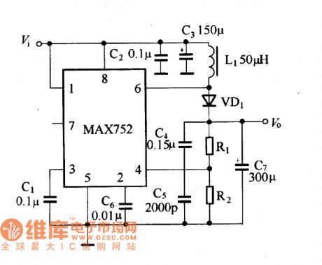
The MAX752 application circuit is as shown in the figure. In this figure, C2 must be close to the chip, this can inhibit the high voltage which is caused by the load fluctuation.
MAX752 application circuit (View)
View full Circuit Diagram | Comments | Reading(451)
A0C56A1125-33 color displayer single chip microcomputer integrated circuit
Published:2011/6/24 7:49:00 Author:Christina | Keyword: color displayer, single chip, microcomputer, integrated circuit
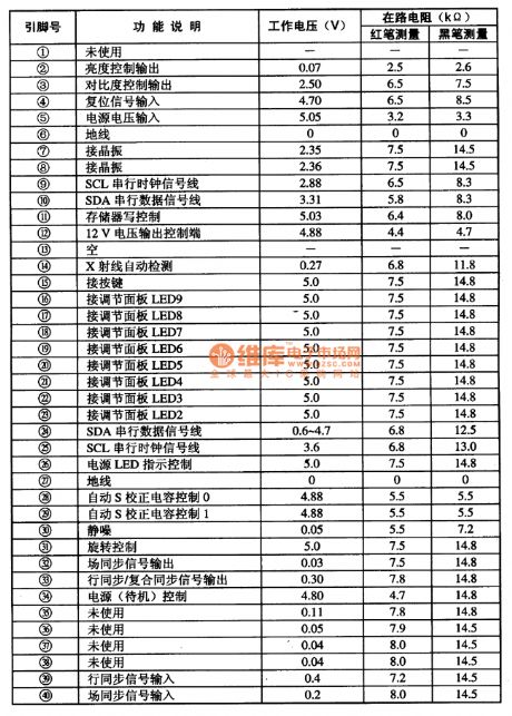
The A0C56A1125-33 is designed as one kind of color displayer single chip microcomputer integrated circuit that can be used in the domestic and imported brands of color displayers such as the TongFang series.etc.
1.Features
The A0C56A1125-33 is composed of the clock oscillating circuit, the reset control circuit, the memory circuit, the I(2)C bus control circuit, the S correction control circuit, the indicator light control circuit, the static noise control circuit, the boot/standby control circuit, the line and field synchronous signal processing circuit, the rotary control circuit, the X-ray detection signal processing circuit and other subsidiary function circuits.
2.Pin functions and data
The A0C56A1125-33 uses the 40-pin dual-row DIP package, the pin functions and data are as shown in table 1.
Table 1 The pin functions and data of the A0C56A1125-33
(View)
View full Circuit Diagram | Comments | Reading(414)
Adjustable switch type voltage stabilizer circuit composed of the LM2577
Published:2011/6/21 1:18:00 Author:Christina | Keyword: Adjustable switch type, voltage stabilizer

The switch type voltage stabilizer circuit which is composed of the LM2577 is as shown in the figure.
The adjustable switch type voltage stabilizer is composed of the LM2577.
(View)
View full Circuit Diagram | Comments | Reading(10124)
UC1846 typical application circuit
Published:2011/6/21 1:09:00 Author:Christina | Keyword: typical application
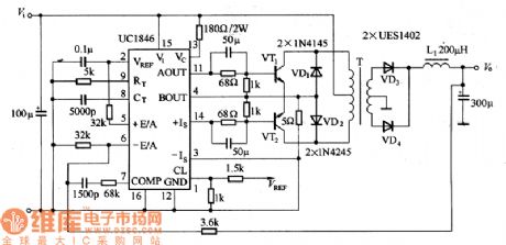
The dual-port output push-scratching type switching voltage regulator, it has the features of excellent performance and low cost.
UC1846 typical application circuit (View)
View full Circuit Diagram | Comments | Reading(1512)
Switch type voltage stabilizer circuit composed of the CW1842
Published:2011/6/21 1:15:00 Author:Christina | Keyword: Switch type, voltage stabilizer

The single port flyback transforming type switch power supply circuit is as shown in the figure, the input voltage is 220V AC.
Switch type voltage stabilizer circuit composed of the CW1842
The output voltage depends on the subprime circle number of T, R2 is the input resistance of CW1842. (View)
View full Circuit Diagram | Comments | Reading(3454)
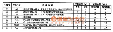
AT24C04 memory integrated circuit
Published:2011/6/24 7:42:00 Author:Christina | Keyword: memory, integrated circuit
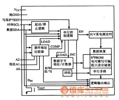
The AT24C04 series memory integrated circuit can be used with the single-chip microcomputer, the stored information is different according to the occasions.
1.Features
The AT24C04 is composed of the I(2)C bus circuit, the E(2)PROM electric erasable programmable read-only memory (ROM), the data byte address/counter circuit.etc. The internal circuit block diagram is as shown in figure 1.
Figure 1 The internal circuit block diagram of the AT24C04
2.Pin functions and data
The AT24C04 uses the 8-pin dual-row DIP package, the pin functions and data are as shown in table 1, this data is measured from the ChangHong CH-10 large screen color TV.
Table 1 The pin functions and data of the AT24C04
(View)
View full Circuit Diagram | Comments | Reading(778)
| Pages:1709/2234 At 2017011702170317041705170617071708170917101711171217131714171517161717171817191720Under 20 |
Circuit Categories
power supply circuit
Amplifier Circuit
Basic Circuit
LED and Light Circuit
Sensor Circuit
Signal Processing
Electrical Equipment Circuit
Control Circuit
Remote Control Circuit
A/D-D/A Converter Circuit
Audio Circuit
Measuring and Test Circuit
Communication Circuit
Computer-Related Circuit
555 Circuit
Automotive Circuit
Repairing Circuit