
Circuit Diagram
Index 1719
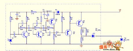
The frequency multiplier circuit
Published:2011/6/22 6:27:00 Author:qqtang | Keyword: frequency multiplier
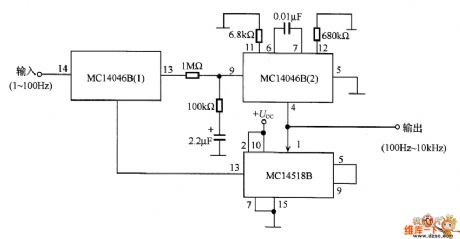
In the figure is the frequency multiplier circuit, the output signal frequency is 100 times of the input one, the frequency range is 1~100Hz. In the circuit, the phaser is MC14046B (1), the voltage control oscillator is MC14046B (2). The voltage control oscillator does the 100 frequency splitting with the 2-bit decimal counter inside it, and the output signal is compared with the input signal which makes the phase synchronize.
This circuit is used to precisely count the low frequency signals which are generated by living organisms in a short time, or used in control pulses of power control acquirement and power supply frequency synchronization. (View)
View full Circuit Diagram | Comments | Reading(2256)
The pulse generating circuit composed of phase-lock loop
Published:2011/6/16 20:40:00 Author:qqtang | Keyword: pulse generating circuit, phase-lock loop
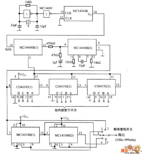
The output frequency of the circuit is 10Hz~999kHz, the frequency precision is 3-bit and adjustable. In the circuit, MCl4046B(1) is the phase comparator, MC14046B(1) is the voltage control oscillator. There are two types of comparators in MC14046B, if the phase clock φ2 is used, the frequency range is 1:1000, to be simple, the maximum adjustable range is 1:10 here. It uses 3-bit digital switch to control the 3 decimal counter, i.e the frequency splitting constants composed of CD40192(1), CD40192(2) and CD40192(3) which set the frequency value.
(View)
View full Circuit Diagram | Comments | Reading(640)
The frequency shift demodulator circuit composed of active filter
Published:2011/6/16 21:09:00 Author:qqtang | Keyword: frequency shift demodulator, active filter
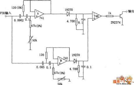
Replacing LC modulation circuit by the active filter, we can avoid using large and expensive inductance coils in frequency shift key control demodulator, it is not only small in size, but also improves the function of the demodulator. This circuit is used to demodulate the 100 byte frequency shift key control signal, whose symbol frequency is 2225Hz, open frequency is 2025Hz. The filter A allows the open frequency to pass, and the filter B allows the symbol frequency to pass, therefore , when the symbol frequency in on the input terminal, the transistor is saturated and the output is short.
(View)
View full Circuit Diagram | Comments | Reading(1898)
The high speed reaction differential pulse generating circuit
Published:2011/6/23 21:01:00 Author:Seven | Keyword: high speed reaction, differential pulse
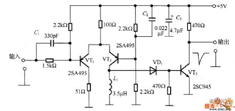
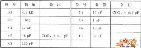
In the circuit, the transistor VT1 and VT2 compose the difference amplifier circuit, to raise the reaction speed, the circuit works in non-saturation state. If the input pulse is 0~+5V, the collecting electrode current is higher than TV2 when it is 0V, if the input is +5v, then the collecting electrode current of VT2 is rising quickly, and the differential waveform is got by L1. VD1 is the Schottky diode of high speed switch, which only allows the forward waveform to conduct VT3. Its basic pole current flows in VT3, then there is collecting electrode current, the LEV is falling quickly and generates a passive differential pulse.
(View)
View full Circuit Diagram | Comments | Reading(872)
The full-digit dual-way controllable silicon circuit
Published:2011/6/23 10:14:00 Author:qqtang | Keyword: full-digit, dual-way, controllable silicon

View full Circuit Diagram | Comments | Reading(461)
The TDA5101A ASK 315 MHz emitter circuit
Published:2011/6/16 20:26:00 Author:qqtang | Keyword: emitter circuit

TDA5101A is an emitter chip with high-power amplifiers, which can be used in the non-key input system, remote control system, communication system and secure system. Its technological features are as follows: the working frequency is 315 MHz; ASK modulation method; the voltage of the power supply is 2.1v~4v; it has low-voltage detection output; the maximum working current is 9mA(emitting function), the standby current is 100nA; it has a efficient power amplifier. The circuit can drive a loop aerial and the current is low, which prolongs the life span of the battery.
(View)
View full Circuit Diagram | Comments | Reading(836)
The 3-key interlock electric switch circuit
Published:2011/6/23 6:26:00 Author:qqtang | Keyword: interlock, electric switch

View full Circuit Diagram | Comments | Reading(552)
The digital frequency shift demodulator circuit (CA3020, MC723 and MC724)
Published:2011/6/16 21:39:00 Author:qqtang | Keyword: frequency shift demodulator
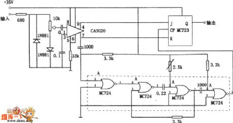
In the figure is the digital frequency shift demodulator circuit. This circuit can be used in frequencies from 1kHz to 10kHz, and it can demodulate the frequency drifting of 1%. The input stage of the circuit consists of the wide band amplifier CA3020, whose differential output is added on the input terminal of J-K trigger. The gate circuit MC724 forms a single stable multi-resonance oscillator. The timing period of the oscillator is equal to the half period of the central frequency. The input signal passes the trigger after being lagged by the oscillator. For example, the 2920Hz means the symbol, the 2750Hz means blank space.
(View)
View full Circuit Diagram | Comments | Reading(593)
The multi-encoding single chip remote control circuit
Published:2011/6/23 10:15:00 Author:qqtang | Keyword: single chip, remote control
View full Circuit Diagram | Comments | Reading(980)
A air-conditioner remote control circuit of CL
Published:2011/6/23 10:17:00 Author:qqtang | Keyword: air-conditioner, remote control
View full Circuit Diagram | Comments | Reading(2714)
The clamping amplifier circuit
Published:2011/6/23 21:32:00 Author:Seven | Keyword: clamping amplifier circuit

In the figure is the clamping amplifier circuit, which is convenient to connect with other circuits. In the distribution of broadcast or all kinds of analog video signals, it is the simplest communication coupling method, for this method, the clamping amplifier is firstly needed to reappear the DC signals. To traditional clamping amplifier, its input terminal is in capacitor coupling way, when using this coupling method, the DC LEV is regulated by forcing the capacitor to discharge during the level blanking period.
(View)
View full Circuit Diagram | Comments | Reading(654)
The air-conditioner mainboard and low-cost PIC16C54 circuit
Published:2011/6/23 10:33:00 Author:qqtang | Keyword: air-conditioner, mainboard

View full Circuit Diagram | Comments | Reading(1091)
Three audio band-pass filters circuit
Published:2011/6/16 6:16:00 Author:John | Keyword: band-pass filter

The figure as shown below is the complete set of three passive audio filters, which can be accessed or out of the circuit. These filters are designed for 500Ω impedance terminal. Three different passbands are available: 1 kHz, 3 kHz and 4 kHz. Filter of 4 kHz is a fifth-order Butterworth (Butterworth) type filter. Filter of 3 kHz is a seventh-order elliptic design followed the Niewiadomski. 1000Hz is reduced from the circuit of 3000Hz. Campbell points out that these filters’ form factor is 2.2:1 and the passband is very flat. ... The corner is smooth with no ripple or self-vibration.”
(View)
View full Circuit Diagram | Comments | Reading(3355)
The LCD display circuit of Angel water dispenser and Samsung 57C2304
Published:2011/6/23 10:52:00 Author:qqtang | Keyword: LCD display, water dispenser

View full Circuit Diagram | Comments | Reading(1174)
The infrared remote control signal converter circuit
Published:2011/6/23 10:12:00 Author:qqtang | Keyword: infrared, remote control, signal converter
View full Circuit Diagram | Comments | Reading(924)
The VMOS pipe switch regulated power supply circuit
Published:2011/6/23 6:38:00 Author:qqtang | Keyword: VMOS, switch, power supply

In the circuit is another VMOS pipe switch regulated power supply circuit. As the circuit is fixed with the voltage comparator 710, so this circuit is simpler than the former one. In the circuit, the resistors (R1, R2 and R3) and the stabilivolts(VD1 and VD2) compose the voltage distribution circuit, the 28V voltage is split into the voltages of 5v, 6v and 18v as the power supply of 710; the resistors(R12 and R13), capacitors C13, diodes(VD6 and VD7) and transistor VT3 compose the power supply soft starting circuit. At the moment of power-on, the starting circuit can make the VT1 drive pulse width of VMOS pipe increase the in index patten.
(View)
View full Circuit Diagram | Comments | Reading(565)
Mazda 95TAURUS (3.8L) engine performance circuit
Published:2011/6/21 0:40:00 Author:John | Keyword: engine performance

Mazda 95TAURUS (3.8L) engine performance circuit is shown. (View)
View full Circuit Diagram | Comments | Reading(547)
The assembled 8-line color lamp controller circuit
Published:2011/6/23 21:23:00 Author:Seven | Keyword: 8-line, color lamp, controller

View full Circuit Diagram | Comments | Reading(574)
HA1394--The 6-8W dual audio power amplifier circuit
Published:2011/6/23 21:12:00 Author:Seven | Keyword: audio power amplifier


HA1394 is the 6-8W dual audio power amplifier circuit, which is produced by Hitachi, Japan. when Vcc=25V and RL=8Ω, the output power of each channel is 8.2w, THD=15%. The circuit is suitable for compounded stereo system and TV audio amplifier, HA1394 is in 12-lead single in-line plastic package, the outline is shown in figure 1.Circuit features:1. Dual audio power amplifier:7-8.2W/channel; 2.few external components(11 capacitors and 6 resistors);3.wide working voltage range, 18-35v; 4. Low noise, low distortion; 5. There is the protection circuit in it.
(View)
View full Circuit Diagram | Comments | Reading(2611)
Mazda 95TAURUS (3.2L, SHO) starting circuit
Published:2011/6/21 0:37:00 Author:John

Mazda 95TAURUS (3.2L, SHO) starting circuit is shown.
(View)
View full Circuit Diagram | Comments | Reading(548)
| Pages:1719/2234 At 2017011702170317041705170617071708170917101711171217131714171517161717171817191720Under 20 |
Circuit Categories
power supply circuit
Amplifier Circuit
Basic Circuit
LED and Light Circuit
Sensor Circuit
Signal Processing
Electrical Equipment Circuit
Control Circuit
Remote Control Circuit
A/D-D/A Converter Circuit
Audio Circuit
Measuring and Test Circuit
Communication Circuit
Computer-Related Circuit
555 Circuit
Automotive Circuit
Repairing Circuit