Circuit Diagram
Index 1718
Mazda 96TAURUS electric seat lumbar circuit
Published:2011/6/21 0:30:00 Author:John | Keyword: electric seat

Mazda 96TAURUS electric seat lumbar circuit is shown.
(View)
View full Circuit Diagram | Comments | Reading(575)
Mazda 96TAURUS (3.4L, SHO) starting circuit
Published:2011/6/21 0:30:00 Author:John

Mazda 96TAURUS (3.4L, SHO) starting circuit is shown.
(View)
View full Circuit Diagram | Comments | Reading(599)
Mazda 96TAURUS defogger circuit
Published:2011/6/21 0:31:00 Author:John | Keyword: defogger

Mazda 96TAURUS defogger circuit is shown.
(View)
View full Circuit Diagram | Comments | Reading(578)
Mazda 96TAURUS light off alarm module circuit
Published:2011/6/21 0:31:00 Author:John | Keyword: alarm module

Mazda 96TAURUS light off alarm module circuit is shown.
(View)
View full Circuit Diagram | Comments | Reading(578)
Mazda 96TAURUS rear wiper washer circuit
Published:2011/6/21 0:31:00 Author:John | Keyword: rear wiper washer

Mazda 96TAURUS rear wiper washer circuit is shown.
(View)
View full Circuit Diagram | Comments | Reading(583)
Mazda 96TAURUS (with DRL) headlight circuit
Published:2011/6/21 0:31:00 Author:John | Keyword: headlight

Mazda 96TAURUS (with DRL) headlight circuit is shown.
(View)
View full Circuit Diagram | Comments | Reading(591)
Mazda 96TAURUS luggage compartment opening circuit
Published:2011/6/21 0:32:00 Author:John | Keyword: luggage compartment

Mazda 96TAURUS luggage compartment opening circuit is shown.
(View)
View full Circuit Diagram | Comments | Reading(566)
Mazda 96TAURUS (automatic) air conditioner circuit
Published:2011/6/21 0:32:00 Author:John | Keyword: air conditioner

Mazda 96TAURUS (automatic) air conditioner circuit is shown.
(View)
View full Circuit Diagram | Comments | Reading(569)
Mazda 96TAURUS body computer circuit
Published:2011/6/21 0:32:00 Author:John | Keyword: body computer

Mazda 96TAURUS body computer circuit is shown.
(View)
View full Circuit Diagram | Comments | Reading(952)
Mazda 96TAURUS Ground distribution circuit
Published:2011/6/21 0:32:00 Author:John | Keyword: Ground distribution

Mazda 96TAURUS Ground distribution circuit is shown.
(View)
View full Circuit Diagram | Comments | Reading(544)
Mazda 96TAURUS electric antenna circuit
Published:2011/6/21 0:32:00 Author:John | Keyword: electric antenna

Mazda 96TAURUS electric antenna circuit is shown.
(View)
View full Circuit Diagram | Comments | Reading(539)
Mazda 96TAURUS airbag circuit
Published:2011/6/21 0:33:00 Author:John | Keyword: airbag

Mazda 96TAURUS airbag circuit is shown.
(View)
View full Circuit Diagram | Comments | Reading(587)
Mazda 96TAURUS speaker circuit
Published:2011/6/21 0:33:00 Author:John | Keyword: speaker

Mazda 96TAURUS speaker circuit is shown.
(View)
View full Circuit Diagram | Comments | Reading(610)
Mazda 96TAURUS electric rearview mirror circuit
Published:2011/6/21 0:33:00 Author:John | Keyword: electric rearview mirror

Mazda 96TAURUS electric rearview mirror circuit is shown.
(View)
View full Circuit Diagram | Comments | Reading(590)
Mazda 96TAURUS (without DRL) headlight circuit
Published:2011/6/21 0:33:00 Author:John | Keyword: headlight

Mazda 96TAURUS (without DRL) headlight circuit is shown.
(View)
View full Circuit Diagram | Comments | Reading(747)
Mazda 96TAURUS electric door lock circuit
Published:2011/6/21 0:34:00 Author:John | Keyword: electric door lock

Mazda 96TAURUS electric door lock circuit is shown. (View)
View full Circuit Diagram | Comments | Reading(841)
The multi-way wireless remote control receiving host circuit
Published:2011/6/23 19:59:00 Author:Seven | Keyword: multi-way, wireless, remote control

In the circuit, when the high frequency receiving component T932 receives the wireless encoding signal from the emitter, after being rectified by the pulse circuit, 2-pin of T932 outputs the restored address code, crossing code, digit code, clock code and other signals, the signal is added on the 10-pin of PT2243, and after it is confirmed by the internal dynamic state decoding scanner, the signal is output from the according connector as a 3-bit digit decoding signal, which can drive 3-bit 7-stage LED screen. The circuit can be connected with other circuit for the user, such as PC management. (View)
View full Circuit Diagram | Comments | Reading(1092)
Mazda 95TAURUS (3.0L) automatic air conditioner circuit
Published:2011/6/21 0:34:00 Author:John | Keyword: automatic air conditioner

Mazda 95TAURUS (3.0L) automatic air conditioner circuit is shown.
(View)
View full Circuit Diagram | Comments | Reading(540)
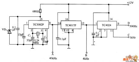
The oscillator circuit composed of frequency integrator circuits
Published:2011/6/23 10:31:00 Author:qqtang | Keyword: oscillator circuit, frequency integrator

In the figure is the oscillator circuit composed of frequency integrator circuits. In the circuit, X is the 10.24MHz crystal oscillator. TC5082P contains a 12-stage frequency splitter, which is widely used. The former oscillating frequency 10.24MHz is split by TC5082P, the 7-pin outputs 10KHz, 6-pin outputs 5KHz, 4-pin outputs 2.5KHz and 8-pin outputs 40KHz, i.e A terminal outputs 40KHz. After being split by TC10I7P, the 12-pin(B terminal) outputs 4KHz, and then split TC4024, 11-pin (C) outputs 1KHz, 9-pin(D) outputs 500Hz, etc. The oscillating frequency can be trimmed by changing C1 and C2.
(View)
View full Circuit Diagram | Comments | Reading(570)
The multiple alarm circuit
Published:2011/6/23 21:41:00 Author:Seven | Keyword: multiple alarm

In the figure is the multiple alarm circuit. The circuit consists of the CA3094 integrated circuit, sensing wire, diode and power supply, etc. The figure in the dotted line frame of the circuit is the alarm switch. In the normal condition, the chip CA3094 6-pin is in a high LEV and the alarm is silent. When one of the sensing wire is broken, short or touch the earth, the 6-pin of the chip will be in a low LEV, so the alarm indicator is pushed to work. The circuit can alarm under conditions of broken circuit, short circuit and ground connection, etc.
(View)
View full Circuit Diagram | Comments | Reading(873)
| Pages:1718/2234 At 2017011702170317041705170617071708170917101711171217131714171517161717171817191720Under 20 |
Circuit Categories
power supply circuit
Amplifier Circuit
Basic Circuit
LED and Light Circuit
Sensor Circuit
Signal Processing
Electrical Equipment Circuit
Control Circuit
Remote Control Circuit
A/D-D/A Converter Circuit
Audio Circuit
Measuring and Test Circuit
Communication Circuit
Computer-Related Circuit
555 Circuit
Automotive Circuit
Repairing Circuit