
Circuit Diagram
Index 1702
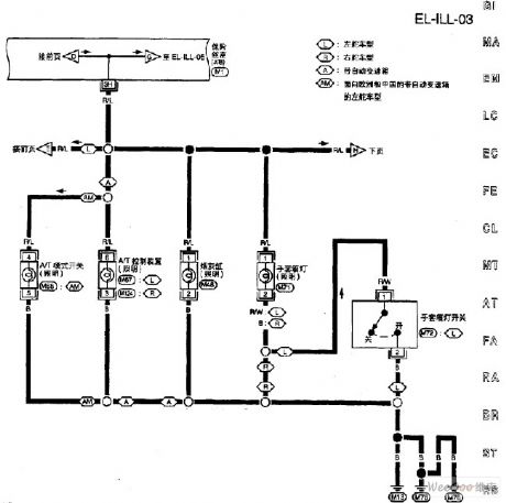
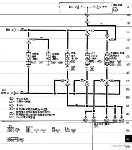
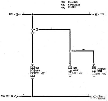
Nissan A32-EL lighting circuit 3
Published:2011/6/22 9:02:00 Author:Nancy | Keyword: Nissan, lighting circuit
View full Circuit Diagram | Comments | Reading(427)
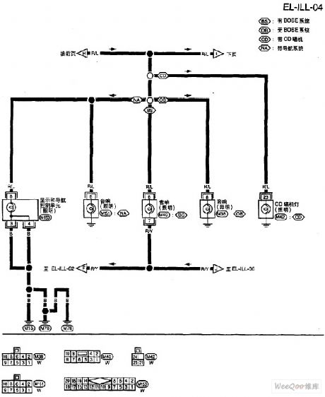
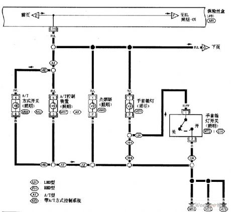
Nissan A32-EL lighting circuit 4
Published:2011/6/22 9:03:00 Author:Nancy | Keyword: Nissan, lighting circuit
View full Circuit Diagram | Comments | Reading(392)
TV antenna amplifier circuit
Published:2011/6/13 8:05:00 Author:Christina | Keyword: TV, antenna, amplifier

The TV antenna amplifier circuit is as shown, the input loop is composed of the L1 and C1, and it plays the frequency selection and the impedance matching function. The first level of the amplifier uses the common emitter - common base amplifier circuit, this kind of circuit has the advantages of high stability and small noise coefficient. The second and third stages of the amplifier are the common emitter circuit, each stage has the tuning circuit. In order to make the amplifier to have the wide pass band, the tuning circuit uses the staggered tuning and adds the resistances R14, R6 and R10 in the oscillation loop. The potentiometer RP1 can be used to adjust the gain of the amplifier.
Figure 15-41 The circuit of the TV antenna amplifier
(View)
View full Circuit Diagram | Comments | Reading(3289)
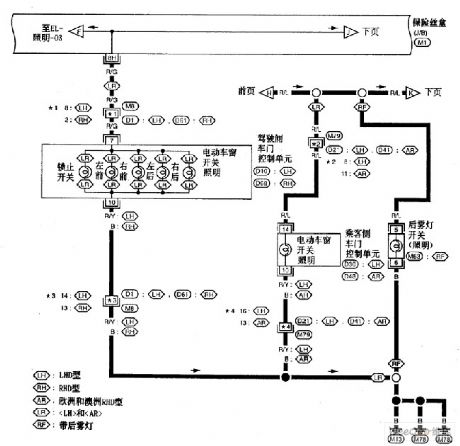
Nissan A32-EL embarkation lamp circuit 1
Published:2011/6/20 9:34:00 Author:Nancy | Keyword: Nissan, embarkation lamp
View full Circuit Diagram | Comments | Reading(421)
Nissan A32-EL interior light circuit 8
Published:2011/6/20 9:32:00 Author:Nancy | Keyword: Nissan, interior light
View full Circuit Diagram | Comments | Reading(371)
Nissan A32-EL interior light circuit 7
Published:2011/6/20 9:31:00 Author:Nancy | Keyword: Nissan, interior light
View full Circuit Diagram | Comments | Reading(394)
1kHz oscillating circuit
Published:2011/6/13 7:49:00 Author:Christina | Keyword: 1kHz, oscillating circuit
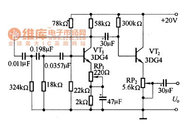
As the figure shows, the oscillating circuit is composed of three RC phase shifting networks with the impedances reduce in turn, the oscillation frequency is 1kHz, the output amplitude is 6V. By adjusting RP1, you can improve the waveform distortion. The oscillation signal is output by the emitter follower which is composed of the VT2.
Figure The 1kHz oscillation circuit
(View)
View full Circuit Diagram | Comments | Reading(624)
The gas-fog alarm circuit of dual-way thyristors
Published:2011/6/25 21:45:00 Author:qqtang | Keyword: gas-fog alarm, dual-way thyristors

The gas-fog alarm circuit of dual-way thyristors When there is the combustible, the conductance of the TGS308 gas sensor is increasing, and it picks out the voltage with the help of potentiometer RP1, the value of the voltage is from 3V to 20V. The raised voltage is then added on transistor VT1 by the diode and the 4.7kΩ resistor, so VT1 is conducting, which makes the dual thyristor 2N6070A conducting. Because of what described above, the full-wave AC voltage pushes H to generate the sound of 90dB, fulfilling the alarm. H is the 20V AC alarm of Deltal6003168.
(View)
View full Circuit Diagram | Comments | Reading(395)
Nissan A32-EL interior light circuit 6
Published:2011/6/20 9:30:00 Author:Nancy | Keyword: Nissan, interior light
View full Circuit Diagram | Comments | Reading(377)
465kHz intermediate frequency signal generator circuit
Published:2011/6/13 7:44:00 Author:Christina | Keyword: 465kHz, intermediate frequency, signal, generator
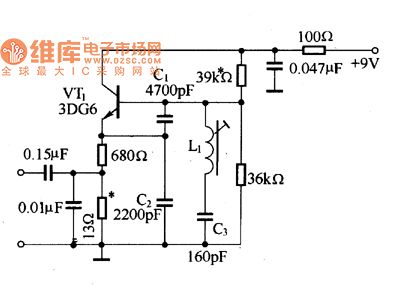
The three-point capacitance oscillator circuit is as shown in the figure, it can produce the 465kHz intermediate frequency signal. In the figure, the resonance loop is composed of the C1, C2, C3 and L1, because the capacity of C1, C2 is larger than the capacity C3, so the oscillation frequency is decided by the C3 and L1
Figure The 465kHz intermediate frequency signal generator circuit
(View)
View full Circuit Diagram | Comments | Reading(1358)
Nissan A32-EL interior light circuit 5
Published:2011/6/20 9:29:00 Author:Nancy | Keyword: Nissan, interior light
View full Circuit Diagram | Comments | Reading(382)
Nissan A32-EL interior light circuit 4
Published:2011/6/20 9:29:00 Author:Nancy | Keyword: Nissan, interior light
View full Circuit Diagram | Comments | Reading(404)
Nissan A32-EL interior light circuit 3
Published:2011/6/20 9:28:00 Author:Nancy | Keyword: Nissan, interior light
View full Circuit Diagram | Comments | Reading(374)
The time base oscillation source circuit of the digital clock
Published:2011/6/20 9:17:00 Author:Nancy | Keyword: Digital clock, time base , oscillation source

The circuit shown is mainly used as a time base oscillation source of the digital clock. The time base output frequency is 60 Hz, suitable for LED digital clock integrate circuit such as LM8361~LM8365, etc. It is a digital clock crystal oscillator time base circuit formed by the I2 bit binary serial counter/divider CC4040 and hex inverter CC4069. (View)
View full Circuit Diagram | Comments | Reading(1149)
AX5206T1 and AX5206T3 fan single chip microcomputer integrated circuits
Published:2011/6/24 7:05:00 Author:Christina | Keyword: fan, single chip, microcomputer, integrated circuits
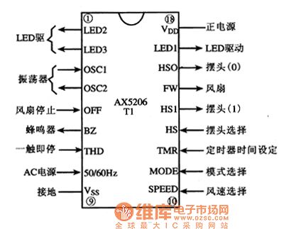
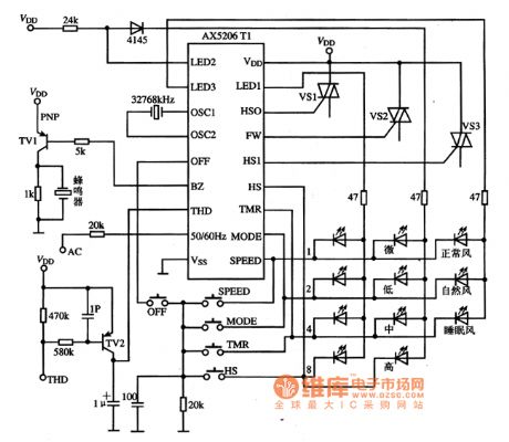
The AX5206T1 is designed as one kind of fan single chip microcomputer integrated circuit which is produced in TaiWan, it can be used in various kinds of fan program control circuits.
1.Pin functions
The AX5206T1 can be used with the single SCR, the AX5206T3 can be used with three SCRs, the pin functions of the AX5206T1 are as shown in figure 1.
Figure 1 The pin functions of the AX5206T1
2.Typical application circuit
The fan program control typical application circuit which is composed of the AX5206T1 is as shown in figure 2.
Figure 2 The typical application circuit of the AX5206T1
(View)
View full Circuit Diagram | Comments | Reading(479)
The photoelectric effect judgment circuit of photocoupler
Published:2011/6/20 8:33:00 Author:Nancy | Keyword: photocoupler, photoelectric effect
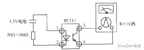
View full Circuit Diagram | Comments | Reading(525)
Nissan A32-EL interior light circuit 2
Published:2011/6/20 9:27:00 Author:Nancy | Keyword: Nissan, interior light

View full Circuit Diagram | Comments | Reading(407)
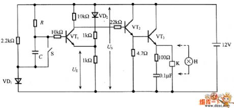
The switching circuit with self-hold function
Published:2011/6/20 8:51:00 Author:Nancy | Keyword: self-hold function, switching circuit

The switching circuit with self-hold function is shown as above. The three photocouplers serve as trigger, self-hold and switch respectively. When there is a start trigger signal added to GY, GG1 conducts, the GY2 and GY3 glow with current flowing through to make GG2 and OG3 conduct. When the trigger signal disappears, GY1 doesn't glow to make GG1 cut off, but GG2 has been conducted, the current of GY2 and GY3 is provided by GG2 path, which is equivalent to saying that the switch continues to connect and the circuit can't recover until the power supply E disappears. (View)
View full Circuit Diagram | Comments | Reading(1300)
The time delay circuit composed of transistors and comparators
Published:2011/6/24 22:55:00 Author:qqtang | Keyword: time delay, transistors, comparators
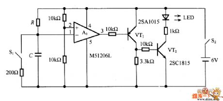
In Figure 2 is the time delay circuit composed of transistors and comparators. The circuit is like the circuit that is shown in Figure 1, the comparing circuit is the comparator integrated chip M51206l, which is not affected by the environment temperature change and power supply voltage change, therefore, it's stable. If VT2 is made of the Darlington power transistor, the circuit can drive large current loading.
Figure 1
Figure 2 (View)
View full Circuit Diagram | Comments | Reading(1954)
The switching circuit composed by photocoupler
Published:2011/6/20 8:35:00 Author:Nancy | Keyword: photocoupler, switching circuit

View full Circuit Diagram | Comments | Reading(560)
| Pages:1702/2234 At 2017011702170317041705170617071708170917101711171217131714171517161717171817191720Under 20 |
Circuit Categories
power supply circuit
Amplifier Circuit
Basic Circuit
LED and Light Circuit
Sensor Circuit
Signal Processing
Electrical Equipment Circuit
Control Circuit
Remote Control Circuit
A/D-D/A Converter Circuit
Audio Circuit
Measuring and Test Circuit
Communication Circuit
Computer-Related Circuit
555 Circuit
Automotive Circuit
Repairing Circuit