
Circuit Diagram
Index 1710
BA5048 infrared emission encoding integrated circuit
Published:2011/6/21 5:07:00 Author:Christina | Keyword: infrared, emission, encoding, integrated circuit
The BA5048 is designed as one kind of multi-channel infrared emission encoding integrated circuit which is produced by the ROHM company, and it can be used in the remote control transmitter of the AV power amplifiers such as the TianYi AD-51OOA power amplifier.
1.Features
The BA5048 is composed of the key pulse generating circuit, the key coding circuit, the clock oscillating circuit, the test circuit, the carrier signal amplifier circuit and other subsidiary function circuits.
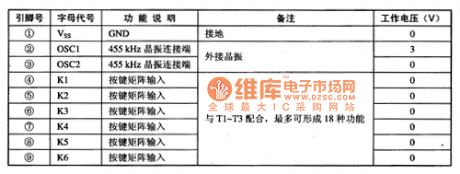
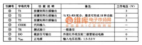
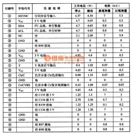
2.Pin functions
The BA5048 is in the 16-pin dual-row DIP plastic package, the pin functions and data are as shown in table 1.
Table 1 The pin functions and data of the BA5048
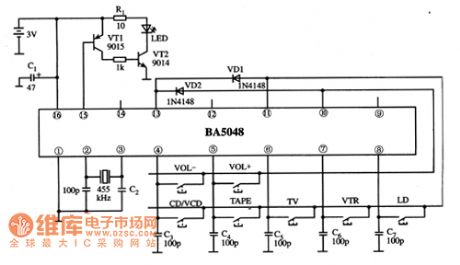
3.Typical application circuit
The remote control transmitter typical application circuit which is composed of the BA5048 is as shown in figure 1.
Figure 1 The typical application circuit of BA5048
(View)
View full Circuit Diagram | Comments | Reading(940)
The single/dual power supply converter circuit
Published:2011/6/23 21:55:00 Author:Seven | Keyword: power supply, converter

TDA2030 is an efficient computing amplifier. With its complementary input stage, we can convert the single pole power supply into two dual pole power supplies that the low-power circuits need.
In the circuit, the resistors of R1 and R2 with the same resistance compose a voltage distributor which makes the upper and lower part have the same voltage. The central point of the distributor is connected with the non-inverting phase input terminal of the amplifier, and the op-amp is assembled into a voltage follower which makes the LEV of O' and O terminal the same. And O' is a vain point, so it has to be separated from the power supply.
(View)
View full Circuit Diagram | Comments | Reading(3586)
AV1428 digital audio and video processing integrated circuit
Published:2011/6/24 7:31:00 Author:Christina | Keyword: digital, audio, video, processing, integrated circuit
The AV1428 is designed as one kind of digital audio and video processing integrated circuit that is produced by the Panasonic company, it can be used in various brands of DAD, VCD players such as the WanLiDa and the Desay series.
1.Features
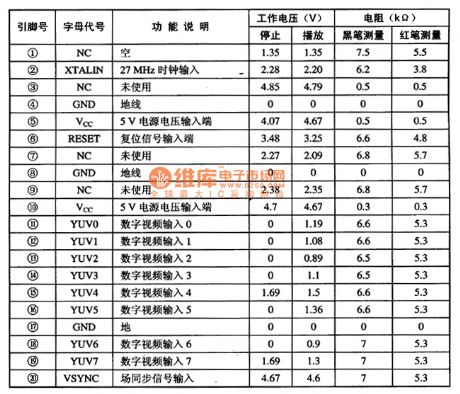
The AV1428 is composed of the NTSC/PAL digital video coding circuit, three 9-bit video DAC and PLL clock synchronous circuits, the audio DAC and audio digital processing circuit. It can be used to change the decompressed video data code signal into the video signal, and it changes the audio data into the analog audio signal.
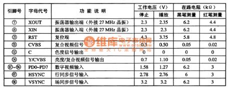
2.Pin functions and data
The AV1428 uses the 100-pin square package, the pin functions and data are as shown in table 1.
Table 1 The pin functions and data of the AV1428
(View)
View full Circuit Diagram | Comments | Reading(427)
BA5104 remote control transmitter integrated circuit
Published:2011/6/21 1:01:00 Author:Christina | Keyword: remote control, transmitter, integrated circuit

The BA5104 is designed as one kind of remote control transmitter integrated circuit that is produced by the Toyo company, and it can be used in various types of remote control transmitters.
1.Pin functions and data
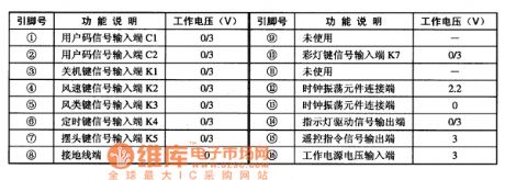
The BA5104 integrated circuit is in the 16-pin dual-row DIP package, the pin functions and data is as shown in table 1.
Table 1 The pin functions and data of the BA5104
2.Typical application circuit
The typical application circuit of the remote controller which is composed of the BA5104 is as shown in figure 1.
Figure 1 The typical application circuit of the remote controller which is composed of the BA5104
(View)
View full Circuit Diagram | Comments | Reading(4489)
The color TV remote control 20 circuit
Published:2011/6/23 22:09:00 Author:Seven | Keyword: color TV, remote control
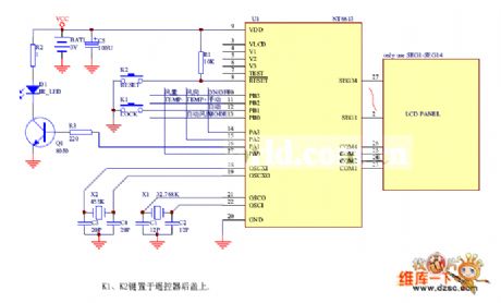
Figure: The color TV remote control 20 circuit (View)
View full Circuit Diagram | Comments | Reading(1115)
The high frequency infrared harmonic stereo headphone circuit
Published:2011/6/23 22:19:00 Author:Seven | Keyword: high frequency, infrared, stereo headphone

The high frequency infrared harmonic stereo headphone circuit is shown as above. (View)
View full Circuit Diagram | Comments | Reading(918)
The color TV remote control circuit (19)
Published:2011/6/23 22:14:00 Author:Seven | Keyword: color TV, remote control

Figure: The color TV remote control circuit (19) (View)
View full Circuit Diagram | Comments | Reading(2259)
The transistor diode bridge rectifier circuit
Published:2011/6/23 22:16:00 Author:Seven | Keyword: transistor diode, bridge rectifier
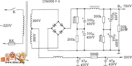
The transistor diode bridge rectifier circuit is shown as above.
(View)
View full Circuit Diagram | Comments | Reading(1797)
AV3169 digital video coding integrated circuit
Published:2011/6/24 7:20:00 Author:Christina | Keyword: digital, video, coding, integrated circuit
The AV3169 is designed as one kind of digital video coding integrated circuit that is produced by the Panasonic company, and it can be used in various brands of DAD, VCD players.
The AV142 integrated circuit is composed of the clock oscillating circuit, the digital video processing circuit, the I(2)C bus interface circuit, the bright color processing circuit.etc. It uses the 44-pin square package, the pin functions and data are as shown in table 1.
Table 1 The pin functions and data of the AV142
(View)
View full Circuit Diagram | Comments | Reading(426)
The transistor diode full-wave rectifier circuit
Published:2011/6/23 22:20:00 Author:Seven | Keyword: transistor diode, full-wave rectifier

The transistor diode full-wave rectifier circuit is shown as above.
(View)
View full Circuit Diagram | Comments | Reading(581)
K5S7C2616B IC Typical Application Circuit
Published:2011/6/22 8:19:00 Author:Robert | Keyword: IC, Typical, Application

The K5S7C2616B is a communication single-chip micro-computer IC which is mainly used as the mobile phone control microprocessor in the cordless telephone.
The KS57C2616B IC's internal part is made up of CPU which is used to control many kinds of commmand signals' input and output, FSK decoding circuit, many kinds of command signals receiving and detecting circuit and resending circuit, and signal path selection circuit, system clock oscillation circuit, transmitting and receiving static double tone/pulse dialing selecting circuit, ring signal detection circuit, indicator light control, LCD liquid crystal display decoder driving circuit and so on.
The comtrol circuit's typical application circuit composed of K5S7C2616B IC is shown in the pictrue.
The picture shows the KS57C2616B IC's typical application circuit. (View)
View full Circuit Diagram | Comments | Reading(541)
The stereo sound valve power amplifier circuit
Published:2011/6/24 4:05:00 Author:Seven | Keyword: stereo sound, valve power, amplifier

The stereo sound valve power amplifier circuit is shown as above.
(View)
View full Circuit Diagram | Comments | Reading(1053)
The color TV remote control circuit (18)
Published:2011/6/23 22:21:00 Author:Seven | Keyword: color TV, remote control
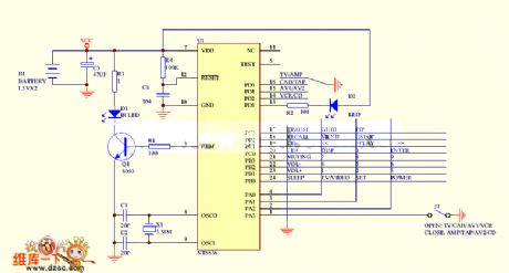
Figure: The color TV remote control circuit (18) (View)
View full Circuit Diagram | Comments | Reading(884)
0~30V continuous adjustable voltage stabilizer circuit
Published:2011/6/23 7:29:00 Author:Christina | Keyword: 0~30V, continuous, adjustable, voltage stabilizer

The 0~30V continuous adjustable voltage stabilizer circuit is as shown in the figure. In the figure, the RP1 is not connected with the ground directly, but it is connected with the potential which is lower than -1.25V. The R3 and VD2 of the circuit supply the -1.3V negative voltage reference, so the circuit can continuously adjust from 0V.
0~30V continuous adjustable voltage stabilizer circuit (View)
View full Circuit Diagram | Comments | Reading(599)
The double purpose desk lamp circuit of dimming and timing
Published:2011/6/24 3:03:00 Author:Seven | Keyword: double purpose, desk lamp

The figured lamp circuit can not only casually regulate the light, but also has the function of timing and putting out the light, which consists of the thyristor light regulating circuit and thyristor time delay circuit, two parts in total.
(View)
View full Circuit Diagram | Comments | Reading(637)
The dual 3-pole valve regulated circuit
Published:2011/6/24 3:25:00 Author:Seven | Keyword: 3-pole valve, regulated circuit

The dual 3-pole valve regulated circuit is shown as above.
(View)
View full Circuit Diagram | Comments | Reading(457)
The low current regulated valve circuit
Published:2011/6/24 2:42:00 Author:Seven | Keyword: low current, regulated valve

The low current regulated valve circuit is shown in the figure.
(View)
View full Circuit Diagram | Comments | Reading(514)
The non-stage regulated sunlight lamp circuit
Published:2011/6/24 2:55:00 Author:Seven | Keyword: non-stage, regulated, sunlight lamp

The non-stage regulated sunlight lamp circuit is shown in the figure, which consists of the regulated circuit, high frequency oscillator and filament transformer. The regulated circuit consists of the two-way thyristor VTH, two-way trigger diode VDH and the resistance-capacitance phase-drifting circuit. By regulating the potentiometer, the conducting angle of the thyristor VTH can be changed, which makes the DC voltage on the two terminals of the sunlight lamp change, so that the aim to regulate the light of the lamp is achieved. VT1 must be the Ge intermediate triode of 3AX818 type, β≥60, Iceo would better be low.
(View)
View full Circuit Diagram | Comments | Reading(541)
Audi alarm system circuit
Published:2011/6/25 10:49:00 Author:John | Keyword: alarm system

View full Circuit Diagram | Comments | Reading(666)
Audi (FQuattro) Anti-lock braking circuit
Published:2011/6/25 10:47:00 Author:John | Keyword: Anti-lock

View full Circuit Diagram | Comments | Reading(551)
| Pages:1710/2234 At 2017011702170317041705170617071708170917101711171217131714171517161717171817191720Under 20 |
Circuit Categories
power supply circuit
Amplifier Circuit
Basic Circuit
LED and Light Circuit
Sensor Circuit
Signal Processing
Electrical Equipment Circuit
Control Circuit
Remote Control Circuit
A/D-D/A Converter Circuit
Audio Circuit
Measuring and Test Circuit
Communication Circuit
Computer-Related Circuit
555 Circuit
Automotive Circuit
Repairing Circuit