
Circuit Diagram
Index 1721
The timing circuit composed of HDl4538
Published:2011/6/21 22:00:00 Author:qqtang | Keyword: timing circuit

In the figure is the timing circuit composed of HDl4538. HDl4538 has many features, for example, when its single steady multi-resonance oscillator is used as the timer, both the positive edge or the passive edge of the pulse can trigger the circuit; the consuming current is low, when the working voltage is 15v, the current is only 15nA; the range of the working voltage is wide, which is 3~18v; the timing set is irrelevant to the working voltage, which is only decided by the external capacitors and the resistance values, the resistance can be 5kΩ~∞, the capacitance is 2000pF~∞.
HDl4538 contains 2 single steady multi-resonance oscillators. (View)
View full Circuit Diagram | Comments | Reading(579)
The TA7344P typical application circuit
Published:2011/6/23 20:30:00 Author:Seven | Keyword: typical application
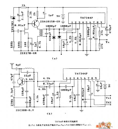
Figure:The TA7344P typical application circuit
Notes: Trl is the high LEV or low LEV output (V&H, V&L); Tx2 is the manifier output(V6(p,P)). (View)
View full Circuit Diagram | Comments | Reading(636)
The low frequency sawtooth wave generating circuit
Published:2011/6/23 20:38:00 Author:Seven | Keyword: low frequency, sawtooth wave
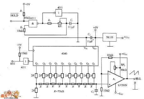
In the figure is the low frequency sawtooth wave generating circuit. The circuit consists of the clock oscillator 4011, IO bit counter 4040, R2-R resistor ladder network, reference voltage generator 78LO5, buffer amplifier A1 and so on. The output wave is a ladder wave which splits the 0~10v into 1024 pieces equally(about 10mV). When the frequency is constant, the rising time can be prolonged by adding C3 and gets a smooth waveform.
(View)
View full Circuit Diagram | Comments | Reading(2148)
The step-up switch power supply circuit
Published:2011/6/23 3:35:00 Author:qqtang | Keyword: step-up, switch power supply

The step-up switch power supply circuit is shown in the figure. When VT1 is conducting, the inductor L is storing energy. When VT1 is blocked, L is inducting a voltage whose left side is passive and right side is positive, the voltage is added on the input voltage, and it provides with power with the help of VD1, which makes the output voltage higher than the input voltage and that forms a step-up switch power supply.
(View)
View full Circuit Diagram | Comments | Reading(631)
The step-down switch power supply circuit
Published:2011/6/23 0:57:00 Author:qqtang | Keyword: step-down, switch power supply

The application circuit of the step-down switch power supply circuit is shown in the circuit. When the switch VT1 is conducting, the diode VD1 is blocked, the input rectified current is charging C with the help of VT1 and L, this circuit increases the energy storage of inductor L. When the switch pipe VT1 is blocked, L is inducting a voltage whose left side is passive and right side is positive, by releasing the energy in L with the help of RL and VD1, the DC voltage is maintained. Whether the voltage is high or low is decided by the pulse width on the basic electrode of VT1.
This circuit needs a few components. (View)
View full Circuit Diagram | Comments | Reading(543)
The NE555 sawtooth wave generator circuit
Published:2011/6/23 21:21:00 Author:Seven | Keyword: sawtooth wave, generator
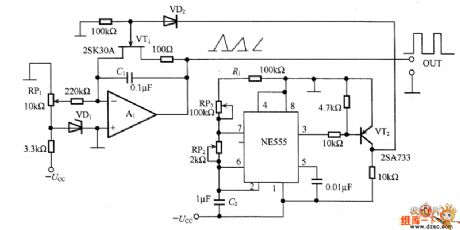
Sawtooth waves can be used as the scanning signal, which are often acquired by capacitor discharging. This circuit maximizes the output voltage and frequency change by changing the reset timing of the integral circuit. In the circuit, A1 is the integrator, when the power is on, A1 is starting to integrating with the set current, when the current reaches the VT1 threshold, VT1 is conducting, the electricity of C1 is released by VT1, after the reset signal is cancelled, the charge is started again, NE555 will output the reset pulse in T=0.693C2(R1+RP2+RP3).
(View)
View full Circuit Diagram | Comments | Reading(2092)
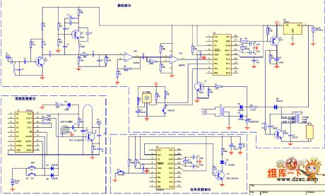
The remote control energy-saving lamp, wireless support and infrared remote control circuit
Published:2011/6/19 20:32:00 Author:qqtang | Keyword: energy-saving lamp, infrared remote control
View full Circuit Diagram | Comments | Reading(500)
The frequency counter circuit
Published:2011/6/21 22:09:00 Author:qqtang | Keyword: frequency counter

In the figure is the frequency counter circuit, the upper limit of the frequency testing range is 10kHz or so, the lower limit is several Hz. In the circuit, the 1st bit is fixed as 0, the testing period is 1.2s, LQT-100X is the module on the market. This circuit can be used as the rotating meter, which is installed in the rotating equipment, for example, the spindle of motors is fixed with encoder of 6 pulses/1 round, so that we can read out the rotating speed each minute of the motor, i.e the digital rotating speed meter.
(View)
View full Circuit Diagram | Comments | Reading(1338)
The HA738 computer charging telephone circuit
Published:2011/6/18 2:06:00 Author:Seven | Keyword: charging telephone

View full Circuit Diagram | Comments | Reading(697)
The Meixintong HL9918 digital recording telephone circuit
Published:2011/6/18 2:10:00 Author:Seven | Keyword: recording telephone


View full Circuit Diagram | Comments | Reading(788)
The geared adjustable DC stabilizer power supply composed of LM317
Published:2011/6/15 2:02:00 Author:Borg | Keyword: DC stabilizer, power supply

View full Circuit Diagram | Comments | Reading(1963)
The 1.25~27V adjustable power supply(NE555 and LM723)
Published:2011/6/15 2:04:00 Author:Borg | Keyword: adjustable power supply

View full Circuit Diagram | Comments | Reading(6379)
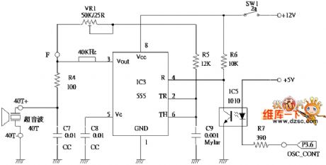
The ultrasonic wave emitting and receiving circuit
Published:2011/6/17 1:07:00 Author:Seven | Keyword: ultrasonic wave, emitting and receiving
View full Circuit Diagram | Comments | Reading(548)
The low-voltage,high-precision and large-current stable power supply of TWH9101
Published:2011/6/15 2:09:00 Author:Borg | Keyword: low-voltage, high-precision, large-current

View full Circuit Diagram | Comments | Reading(652)
The infrared wireless headphone circuit
Published:2011/6/19 0:24:00 Author:Seven | Keyword: wireless headphone
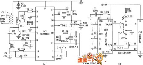
As the inductive wireless headphone emitter must be fixed on the wall or the ceiling of the room, it can't be used outside, which is the weakness of inductive wireless headphones. But the infrared wireless headphone is different, as its signal is emitted by a portable infrared emitting circuit, which can not only be used in e-teaching, domestic TV and stereo equipment audio signal wireless reception, but also used in outdoor portable radios, CD, VCD and MP3 without wires, so it is a real walkman .
(View)
View full Circuit Diagram | Comments | Reading(1682)
The random frequency doubler composed of CH7555
Published:2011/6/17 7:23:00 Author:Borg | Keyword: random frequency doubler
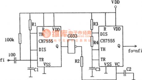
Usually, the frequency doubler composed of phase-lock loop has good functions, and it can get a high frequency multiply ratio, but the construction of the circuit is complex and it's costly. However, the homogenization of the output which is generated in the method of edge detection is bad. The figured circuit characterizes simpleness, wide dynamic range, good homogenization and so on. In the figure, the CH7555 timer is converted into a common multi-resonance oscillator on the right side, the rising of the control voltage will lead to the dropping of the output frequency. The input reaches the single stable circuit firstly. (View)
View full Circuit Diagram | Comments | Reading(753)
The multi-function radio principle circuit
Published:2011/6/17 0:26:00 Author:Seven | Keyword: multi-function radio
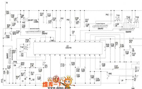
Notes: the audio signal which is output from 23-pin of u1 is coupled by C123 and input from 24-pin. W1 is the electric sound volume control potentiometer, which controls the sound volume of 4-pin of u1. The output audio signal of 23-pin of u1 is sent to the IC internal power amplifier of 24-pin of c1, after being amplified, the audio signal is output from 27-pin to drive the loudspeaker or headphone. The clock control and drive display circuit consists of the LED screen (ICD), SC361O, x1, c1, c6, R1-R5, swl-SW8, Q1 and other elements. (View)
View full Circuit Diagram | Comments | Reading(1014)
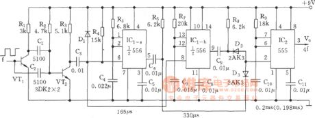
The 4-time frequency multiply circuit (555)
Published:2011/6/17 6:57:00 Author:Borg | Keyword: frequency, multiply circuit
View full Circuit Diagram | Comments | Reading(611)
The 555 single stable circuit as the frequency splitter
Published:2011/6/17 6:52:00 Author:Borg | Keyword: single stable circuit, frequency splitter
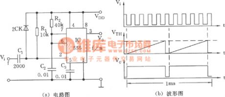
(a) circuit (b) waveform diagram (View)
View full Circuit Diagram | Comments | Reading(628)
The efficient stable power supply (LM334)
Published:2011/6/15 1:42:00 Author:Borg | Keyword: stable power supply

View full Circuit Diagram | Comments | Reading(907)
| Pages:1721/2234 At 2017211722172317241725172617271728172917301731173217331734173517361737173817391740Under 20 |
Circuit Categories
power supply circuit
Amplifier Circuit
Basic Circuit
LED and Light Circuit
Sensor Circuit
Signal Processing
Electrical Equipment Circuit
Control Circuit
Remote Control Circuit
A/D-D/A Converter Circuit
Audio Circuit
Measuring and Test Circuit
Communication Circuit
Computer-Related Circuit
555 Circuit
Automotive Circuit
Repairing Circuit