
Circuit Diagram
Index 1731
The soft-starting control signal generating circuit
Published:2011/6/20 21:17:00 Author:Seven | Keyword: soft-starting, control signal
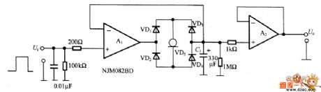
See as the figure, this is a soft-starting control signal generating circuit, it is used in the output voltage soft-starting of the power supply circuit , the signal source is controlled by the control signal or the motor with little mechanical shock. The output current of constant current diode VD5 charges CI and gets a linear rising/dropping waveform. A1 and A2 are the FET input computing amplifier NJM082BD whose bias current is low. The circuit linear rising signal is compared with the triangular wave by the comparator, then the wide pulse modulation PWM signal is generated.
(View)
View full Circuit Diagram | Comments | Reading(539)
The electric whistle alarm circuit
Published:2011/6/23 11:07:00 Author:qqtang | Keyword: electric whistle alarm
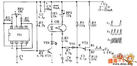
In the figure is the electric whistle alarm circuit that can generate the rising and falling tone sound. The sound is generated by two generators (timer 555 and single knot transistor 2N2648) that are coupled by the photoelectric coupler; The 555 generator produces the 0.3HZ frequency signal, which makes the single knot transistor VT2 sound generator strengthen or weaken in this rhythm.
(View)
View full Circuit Diagram | Comments | Reading(889)
The 555 time delay energy-saving lamp circuit
Published:2011/6/23 10:59:00 Author:qqtang | Keyword: time delay, energy-saving lamp

In the circuit is the 555 time delay energy-saving lamp circuit, which can be used at the stair exit and corridor. By pressing S1, the relay K is conducting, at the same time, the lamp K is glowing, the touch spot K1 is closed and locking the power supply. H is put out in 2min, after the light is off, the power consumption is very low, so the aim of saving power is fulfilled.
(View)
View full Circuit Diagram | Comments | Reading(1595)
The 555 auto dark room exposure circuit
Published:2011/6/23 4:02:00 Author:qqtang | Keyword: dark room, exposure

In the figure is the 555 auto dark room exposure circuit. The switch S is the timing gear, when pressing S1, the 3-pin of 555 is outputting a high LEV, the relay K is conducting, the touch spot K1 is closed, lamp h is lighting and exposing, and it is put out in certain. Press S1 again, the exposure will be done again, RP2 is used to adjust the exposure time, which is from 1s to 1min. After the switch S2 is connected with 1, it is working with phototransistor VT and the exposure is done automatically, when it is connected with S, it becomes focusing, and becomes timing by being connected with 3. When S3 is connected, it's manual mode.
(View)
View full Circuit Diagram | Comments | Reading(1154)
The 3-phase sine signal generator circuit
Published:2011/6/20 22:39:00 Author:Seven | Keyword: 3-phase, sine signal
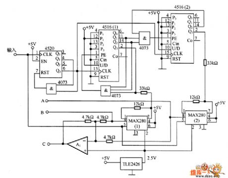
In the figure is the 3-phase sine signal generator circuit. This kind of circuit is widely used, such as controlling the voltage of the synchronized motor rotor. In the circuit, 2 dual-counters 4516(1)and 4516(2) with the low-pass filters MAX280(1) and MAX280(2) generate the phase-A and phase-B signals of sine waveform, and the signals are added together by A1 and then there generates an inverting phase signal of C. To reduce the distortion of the waveform, the counter outputs symmetric signals, and the phase different would better be 120°.
(View)
View full Circuit Diagram | Comments | Reading(4025)
ICL7107--the integrated control module circuit
Published:2011/6/23 10:50:00 Author:qqtang | Keyword: integrated control, module circuit

ICL7107 is a widely used integrated circuits. It contains a 3 1/2 bit digital A/D converter, which can directly drive LED digit pipes, and in it there sets the reference voltage, independent analog switch, logic control, display drive, auto reset functions and so on. Here, we introduce a type of its application circuit production--the digit voltmeter, and its circuit is in the figure. When we manufacture it, we choose the common positive digit pipes as the display, the multiple turn resistor as the 2K adjustable resistor and the metal film resistor with little difference as the divider resistor.
(View)
View full Circuit Diagram | Comments | Reading(2680)
The single spot injection circuit of Jinbei-Sea lion SY6480A2F-E bus
Published:2011/6/23 3:29:00 Author:qqtang | Keyword: single spot, injection circuit, Jinbei
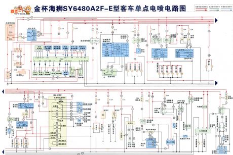
The single spot injection circuit of Jinbei-Sea lion SY6480A2F-E bus is shown as above.
(View)
View full Circuit Diagram | Comments | Reading(580)
The NE555 timing circuit of ±15v power supply
Published:2011/6/23 3:24:00 Author:qqtang | Keyword: timing circuit, power supply

In the figure is the NE555 timing circuit of ±15v power supply. In the circuit, to get a dual-channel capability and work in double power supplies, we can add a floating different working voltage on the power supply terminal of NE555. The resistors R1~R4 and transistors (VT1 and VT2) compose a LEV moving net, which can generate the required floating voltage. The capacitor C1 is used to impede the high frequency oscillation generated by the impedance timer when it is jumping.
(View)
View full Circuit Diagram | Comments | Reading(2735)
The working principle circuit of the infrared remote control mouse
Published:2011/6/23 2:41:00 Author:qqtang | Keyword: working principle, remote control
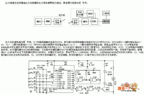
The infrared remote control mouse consists of the infrared emitter and receiver, whose principle circuit is shown in the figure. The infrared emitter is shown in the figure. IC1 is the encoder integrated circuit VD5026, and it is coupled with VD5027 and VD5028. The 1~8-pin of VD5026 are the address terminals A0~A7, 10~13-pin are the data terminals D0~D3 (when working with VD5028, they can be the address terminals A8~A11), 17-pin is the output terminal of the encoding signal, and its output signal modulates the signals of the 40KHz pulse generator composed of IC2A and IC2D.
(View)
View full Circuit Diagram | Comments | Reading(1068)
The long-timing circuit of NE555
Published:2011/6/23 3:16:00 Author:qqtang | Keyword: long-timing

In the figure is the long-timing circuit of NE555. In the circuit, NE555 outputs a high LEV after it is triggered and the transistor in 7-pin is broken down. The integrator engages in linear integration to the reference voltage Uref generated by the resistor voltage, the integration output is rising along the line of Uref/(RC), the 6-pin trigger spot is (2/3)Ucc=10V. If Uref=0.1V, the delayed time that the threshold value UTH of NE555 rises to 10V is 100RC. When it reaches 2/3Ucc, the trigger in NE555 is reversing and the output of 3-pin is turning into a low LEV from a high LEV.
(View)
View full Circuit Diagram | Comments | Reading(798)
The DTMF wireless calling system circuit
Published:2011/6/21 1:49:00 Author:Seven | Keyword: wireless calling system

By the dual sound multi-frequency encoding signal, the circuit modulates the emitted carrier frequency, and it composes a DTMF encoding wireless calling system circuit. The circuit uses DTMF encoding circuit UM97085 and decoding circuit YN9101 to form a micro wireless calling system, which is used in small enterprises, and it is convenient and economic. See as the figure, (a) represents the DTMF encoding wireless electric emitting circuit, (b) represents the wireless electric reception demodulating, DTMF decoding and stereo signal sound system.
(View)
View full Circuit Diagram | Comments | Reading(2213)
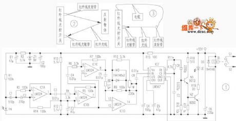
The infrared circuit principle diagram
Published:2011/6/23 2:43:00 Author:qqtang | Keyword: infrared circuit, principle diagram
View full Circuit Diagram | Comments | Reading(528)
The broken and short multi-line stereo alarm circuit
Published:2011/6/22 3:54:00 Author:Borg | Keyword: multi-line, alarm circuit

In the figure is the broken and short multi-line stereo alarm circuit. The alarm consists of the rectifier power supply, stereo part, 5 short lines and 5 broken lines of alarm and control circuits. The rectifier power supply consists of D11~D14,R11,C11,D10 and so on, the stereo alarm circuit consists of IC2(NE555) and IC3(NE555), etc. IC4(BA532) is the power amplifier circuit, whose output power can reach 5W. The short or touch alarm part consists of 6-phase inverter IC1(CD4069), BG1, BG2 and so on, when the human body touches either terminal of A~E, as the input terminal of the OR gate is in a low LEV.
(View)
View full Circuit Diagram | Comments | Reading(705)
The XTR110 disorder and span adjusting circuit
Published:2011/6/22 2:37:00 Author:Borg | Keyword: disorder, span adjusting

In the figure is the malfunction and span adjusting circuit of 0~10v input voltage and 4~20mA output current. R1 is the disorder adjusting potentiometer, R2 is the span adjusting potentiometer.
Disorder adjusting method: input a low voltage that is not 0, adjust R1 and make the output have a right current value, and then make the input be 0, so that the output must be 0. Span adjusting method: the set input voltage as full scale +10v, adjust R2 to make the current reach to top limit of 20mA. What need to be noticed is that the span adjustment will affect the disorder adjustment. (View)
View full Circuit Diagram | Comments | Reading(1012)
The 8-line digital display superior alarm circuit
Published:2011/6/22 3:08:00 Author:Borg | Keyword: 8-line, display, alarm circuit

In the figure is the 8-line digital display superior alarm circuit. This circuit consists of the timed stereo circuit, 8-line encoder, decoder, digital display circuit and so on. IC1(CD4532) is the octal prior encoder, and the 8-line input control wires are connected with K0~K7 eight switches, when the input control wire is cut off due to some condition, then input a corresponding high LEV, the encoder will program a 3-bit binary address code. If there are more than 2 lines of wires cut off, the encoder will react to the line of the superior stage.
(View)
View full Circuit Diagram | Comments | Reading(1515)
The high voltage code protection alarm circuit
Published:2011/6/22 1:57:00 Author:Borg | Keyword: high voltage, protection

In the circuit is the high voltage code protection alarm circuit. The alarm uses resistance code to recognize the true or false, so it can be used to the door, window, handbag, lock case and so on. The core of the circuit is the multi-resonance oscillating stereo circuit, the chip CD4069 and transformer B are used as the drive stage. In the circuit, when a and b is broken down or short, the resistance of the resistor Rx may rise or fall, which leads to the high output LEV of F4 OR gate circuit(e point), so the pipe BG1 is conducting, and the stereo circuit is passable, which generates the dual sound alarm signals.
(View)
View full Circuit Diagram | Comments | Reading(716)
AC power control photocell memory switch circuit
Published:2011/6/22 3:20:00 Author:TaoXi | Keyword: AC, power control, photocell, memory switch

We can use the flash beam to supply the remote control for the AC power devices. The important point of this device is the memory function. It can continuously supply the power to the device. When it acts the second time, the power will be cut off continuously. It is composed of a high sensitivity photocell, a high-gain integrated circuit Schmitt trigger and a pulse-driven locking relay.
(View)
View full Circuit Diagram | Comments | Reading(2855)
Precise light diode comparator circuit
Published:2011/6/22 3:26:00 Author:TaoXi | Keyword: Precise, light diode, comparator
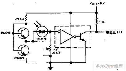
The R1 sets the comparison level. When it is comparing, the voltage drop of the light diode is lower than 5mV, the dark current reduces a magnitude. The integrated circuit is LM111/211/311.
(View)
View full Circuit Diagram | Comments | Reading(619)
RF transmission power amplifier circuit
Published:2011/6/22 19:59:00 Author:TaoXi | Keyword: RF, transmission, power amplifier

The RF transmission power amplifier uses the 50~850MHz power amplifier chip SBB-2089, the power gain is 20dB, the transceiver distance is about 150m, so it can be used in the traffic information reminding. Even you have not permit by the committee, you can further expand the receiving range. The power amplifier circuit is as shown in the figure.
(View)
View full Circuit Diagram | Comments | Reading(1188)
Shaft rotation status detection circuit
Published:2011/6/22 19:24:00 Author:TaoXi | Keyword: Shaft, rotation, status, detection circuit

The shaft rotation status detection circuit: there are some electromagnetic sensors around the shaft, these sensors make the spring switch to turn on and off. When the switch is at the on position, the monostable multivibrator is triggered, the Q outputs the H, the operating is normal, Q maintains the H state. When the shaft stops turning, the switch can not turns on and off, after the Cx and Rx confirm the time constant, the output of Q is L.
(View)
View full Circuit Diagram | Comments | Reading(602)
| Pages:1731/2234 At 2017211722172317241725172617271728172917301731173217331734173517361737173817391740Under 20 |
Circuit Categories
power supply circuit
Amplifier Circuit
Basic Circuit
LED and Light Circuit
Sensor Circuit
Signal Processing
Electrical Equipment Circuit
Control Circuit
Remote Control Circuit
A/D-D/A Converter Circuit
Audio Circuit
Measuring and Test Circuit
Communication Circuit
Computer-Related Circuit
555 Circuit
Automotive Circuit
Repairing Circuit