Circuit Diagram
Index 1726
The MCl45028 logic frame circuit
Published:2011/6/19 3:05:00 Author:Seven | Keyword: logic frame circuit

The logic frame circuit
The MCl45028 logic frame circuit (View)
View full Circuit Diagram | Comments | Reading(462)
The 3-terminal dual adjustable regulated power supply circuit
Published:2011/6/19 3:19:00 Author:Seven | Keyword: 3-terminal, power supply


The 3-terminal adjustable regulated power supply circuit adjusts the output voltage by external resistors, to be sure the precision and stability of the output voltage, we should choose the precise resistor, and the resistor must be close to the regulator, prevent the output current from generating faulted voltage on the lines. In the figure is the application circuit of a 3-terminal dual adjustable regulated power supply, whose output voltage is:
In the figure is the 3-terminal dual adjustable regulated power supply circuit composed of LMLMl17and LM137. The figured VREF is equal to V31. (View)
View full Circuit Diagram | Comments | Reading(1407)
The +5V-+12V booster power supply (MAX761)
Published:2011/6/14 20:42:00 Author:Borg | Keyword: booster power supply
View full Circuit Diagram | Comments | Reading(1266)
The self-bias frequency booster converting power supply composed of MAX630
Published:2011/6/14 20:41:00 Author:Borg | Keyword: frequency, booster, power supply
View full Circuit Diagram | Comments | Reading(617)
The ultra-small PWM DC/DC booster voltage stable power supply
Published:2011/6/14 4:26:00 Author:Borg | Keyword: ultra-small, DC/DC, power supply
View full Circuit Diagram | Comments | Reading(634)
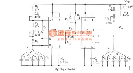
The variable frequency and pulse width waveform generator (555)
Published:2011/6/13 21:13:00 Author:Borg | Keyword: variable frequency, pulse width
View full Circuit Diagram | Comments | Reading(2053)
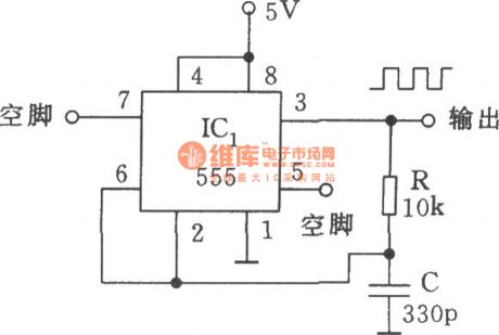
The square wave generator of 555, R and C
Published:2011/6/13 21:10:00 Author:Borg | Keyword: square wave
View full Circuit Diagram | Comments | Reading(1003)
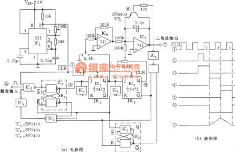
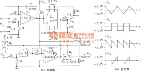
The triangular and square wave generator circuit (555)
Published:2011/6/13 21:09:00 Author:Borg | Keyword: triangular, square wave
View full Circuit Diagram | Comments | Reading(849)
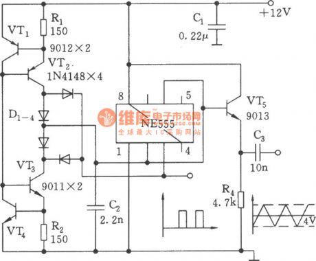
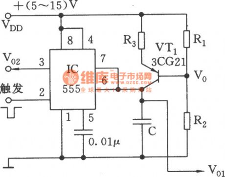
The changeable triangular wave generator (555)
Published:2011/6/13 21:08:00 Author:Borg | Keyword: changeable, triangular wave generator
View full Circuit Diagram | Comments | Reading(542)
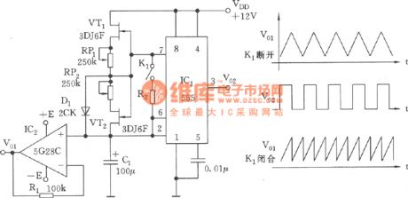
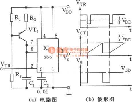
The simple linear sawtooth wave generator circuit composed of 555
Published:2011/6/14 4:09:00 Author:Borg | Keyword: sawtooth wave, generator
View full Circuit Diagram | Comments | Reading(761)
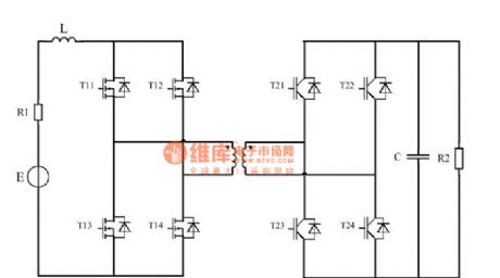
The dual-way DC/DC converter circuit
Published:2011/6/14 4:22:00 Author:Borg | Keyword: dual-way, DC/DC converter
View full Circuit Diagram | Comments | Reading(556)
The multiple wave outline generator of 555 (2)
Published:2011/6/13 21:04:00 Author:Borg | Keyword: multiple, wave outline
View full Circuit Diagram | Comments | Reading(602)
The multiple wave outline generator of 555 (1)
Published:2011/6/13 21:03:00 Author:Borg | Keyword: multiple, wave outline generator
View full Circuit Diagram | Comments | Reading(495)
The step-up stable power supply and battery back-up power supply composed of TL499A
Published:2011/6/14 20:50:00 Author:Borg | Keyword: stable power supply, battery, back-up power supply
View full Circuit Diagram | Comments | Reading(867)
The TC9153AP audio control circuit
Published:2011/6/20 22:02:00 Author:Seven | Keyword: audio control circuit
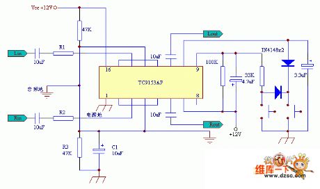
The TC9153AP audio control circuit is shown in the above figure.
(View)
View full Circuit Diagram | Comments | Reading(4802)
The application circuit of M58485P
Published:2011/6/19 3:21:00 Author:Seven | Keyword: application circuit
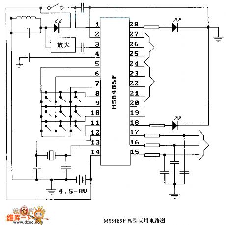
The application circuit of M58485P (View)
View full Circuit Diagram | Comments | Reading(992)
The M58485P logic frame circuit
Published:2011/6/19 3:22:00 Author:Seven | Keyword: logic frame circuit
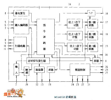
The M58485P logic frame circuit (View)
View full Circuit Diagram | Comments | Reading(601)
The IM3886 op-amp circuit
Published:2011/6/20 22:02:00 Author:Seven | Keyword: op-amp


The IM3886 op-amp circuit is shown in the above circuit.
(View)
View full Circuit Diagram | Comments | Reading(886)
The precise rectifier circuit with the integrating sub-circuit
Published:2011/6/19 3:36:00 Author:Seven | Keyword: precise rectifier, integrating sub-circuit
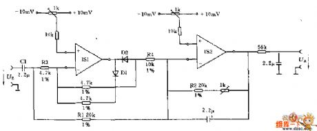
This circuit can switch the input DC signal into the DC signal. If the input signal is in a very low frequency, the input terminal capacitor C1 can be omitted.
In the forward half-cycle, the output terminal of op-amp IS1 is connected by diode D1, and it is separated in the same phase by D2. The op-amp IS2 is working as the inverting voltage follower. In the backward half-cycle, IS1 is the phase inverter and it is connected with the summing point by R2. On the input terminal, R3 and R2 compose a passive feedback circuit. (View)
View full Circuit Diagram | Comments | Reading(660)
The 555 square wave and sawtooth wave generator
Published:2011/6/13 20:53:00 Author:Borg | Keyword: square wave, sawtooth wave
View full Circuit Diagram | Comments | Reading(2042)
| Pages:1726/2234 At 2017211722172317241725172617271728172917301731173217331734173517361737173817391740Under 20 |
Circuit Categories
power supply circuit
Amplifier Circuit
Basic Circuit
LED and Light Circuit
Sensor Circuit
Signal Processing
Electrical Equipment Circuit
Control Circuit
Remote Control Circuit
A/D-D/A Converter Circuit
Audio Circuit
Measuring and Test Circuit
Communication Circuit
Computer-Related Circuit
555 Circuit
Automotive Circuit
Repairing Circuit


