
Circuit Diagram
Index 1724
Serial adjustable voltage regulator circuit
Published:2011/6/15 4:55:00 Author:John | Keyword: Serial adjustable voltage regulator

Serial adjustable voltage regulator circuit is shown below.
(View)
View full Circuit Diagram | Comments | Reading(871)
The high input voltage integrated stable power supply circuit composed of CW7800 (2)
Published:2011/6/14 4:14:00 Author:Borg | Keyword: input voltage, power supply

View full Circuit Diagram | Comments | Reading(468)
Universal Active Filter circuit
Published:2011/6/15 10:40:00 Author:John | Keyword: Universal Active Filter

Universal Active Filter circuit is shown below.
Referring to the circuit as shown, its center frequency f0 = 3.4kHz, notch frequency fc = 9.5kHz and quality factor Q = 3.4. Transfer coefficient is 0.1for the high-frequency filter and is 1 for the band pass filter or the low-frequency filter. And 10.f0Q ≤ 200kHz is for the notch filter. When the output sinusoidal signal is with 10V, its highest frequency is not more than 200kHz.
(View)
View full Circuit Diagram | Comments | Reading(1122)
The KJT1 adjustment control board circuit principle diagram
Published:2011/6/18 2:48:00 Author:Seven | Keyword: adjustment control board, principle diagram
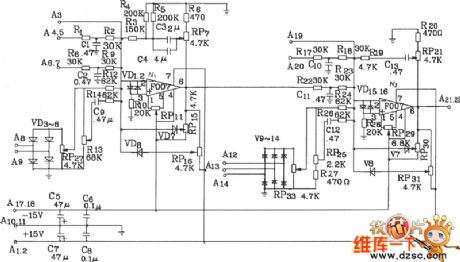
The KJT1 adjustment control board circuit principle diagram with graph paper.The KJT1 adjustment control board consists of the 2-stage computing amplifier, which has the proportional integral sector circuit and a speed dual closed-loop system. This PI adjustment board can work with KJZ2, KJZ3 , KIz6 and other controllable silicon distribution boards, it can fulfill functions of single phase, 3-phase AC voltage adjustment, speed adjustment or AC voltage adjustment and speed adjustment. It has a good quality and convenient usage. The KJTI adjustment control board circuit is shown in the figure.
(View)
View full Circuit Diagram | Comments | Reading(730)
The general triangular wave generating circuit (741)
Published:2011/6/14 0:24:00 Author:Borg | Keyword: triangular wave

In the figure is the general triangular wave generating circuit (741). In the circuit, the computing amplifiers of A1 and A2 is the positive/passive peak value detector, A3 is the integrator, C1 is the holding capacitor. This circuit can adapt to the temperature of wide range, which has good linearity and amplitude stabilization. The oscillating frequency depends on the time constant R3C2, if Va=8V, the frequency is 1KHz. The ratio between C1 and C2 is 20:1. The computing amplifier is 741. (View)
View full Circuit Diagram | Comments | Reading(525)
The square wave generating circuit composed of LM139
Published:2011/6/14 21:02:00 Author:Borg | Keyword: square wave, circuit
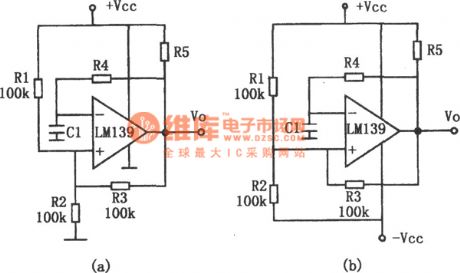
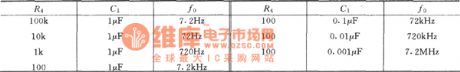
In the figure is the square wave generating circuit. LM139 can be used in oscillating circuits of a few MHZ. This circuit is the square wave generating circuit which consists of few elements. The output frequency of the circuit is decided by the time parameters of R4 and C1, and it is also decided by the lag circuits of R1,R2 and R3. The maximum working frequency is limited by the lagged time of the comparator large signal transmission. Besides, the working frequency is relevant to the loading characteristics. When the circuit is capacitive load, its maximum working frequency is reduced. In the circuit, figure (a) is the single power supply circuit.
(View)
View full Circuit Diagram | Comments | Reading(540)
The adjustable symmetric triangular wave generator(NE555)
Published:2011/6/14 0:52:00 Author:Borg | Keyword: symmetric, triangular wave generator
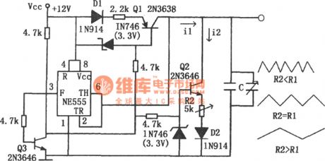
In the circuit, the timer NE555 forms a triangular wave generator, whose working frequency can reach 100KHz or so. The transistors Q1 and Q2 in the figure form a switch constant current power supply whose state is controlled by Q3. When Q3 is conducting, the collector electrode is in the low LEV, at the moment, Q1 is conducting and charging the capacitor C with the constant current of i1, the voltage on the two terminals of C is a linear slope wave. When the two terminals of capacitor C are in a voltage of 2E/3 (the high trigger LEV of the timer), the 3-pin of the timer is in a low LEV, Q3 is blocked and the collecting electrode is in a high LEV. (View)
View full Circuit Diagram | Comments | Reading(2275)
The sine, square and triangular wave generator(NE566、NE531)
Published:2011/6/14 1:48:00 Author:Borg | Keyword: triangular wave, generator
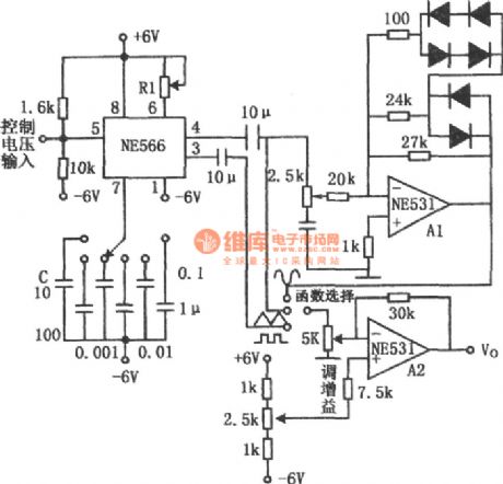
In the figure is sine, square and triangular wave generator. This circuit consists of a voltage control oscillator and two high-speed op-amps, which has a wide frequency range. The oscillator is formed by NE566, whose working frequency range is 0.1Hz~1MHz. Frequency adjustment is done by R1 and C. The triangular and square waves are imposed on the computing amplifier A2 by communication coupling, and they are output by A2. The sine wave converter A1 can switch the triangular wave into the square wave, and the waves are output by A2. The output frequency of the sine wave is 10Hz~1MHz, which is switched by the diode. (View)
View full Circuit Diagram | Comments | Reading(3933)
The M50117F/AP/BP/CP logic frame circuit
Published:2011/6/18 2:50:00 Author:Seven | Keyword: logic frame circuit
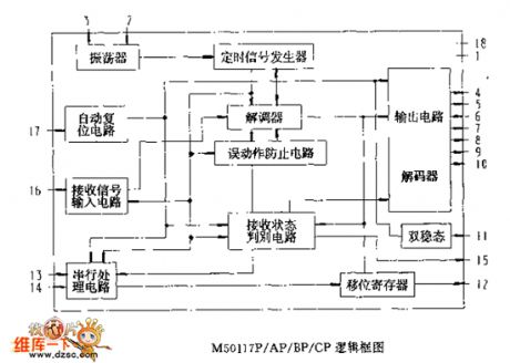
The M50117F/AP/BP/CP logic frame circuit (View)
View full Circuit Diagram | Comments | Reading(407)
The 6SN7+300B single terminal circuit
Published:2011/6/20 22:01:00 Author:Seven | Keyword: single terminal circuit

The 6SN7+300B single terminal circuit is shown in the figure.
(View)
View full Circuit Diagram | Comments | Reading(6748)
The stable square wave and triangular wave generator (118)
Published:2011/6/14 1:18:00 Author:Borg | Keyword: square wave, triangular wave
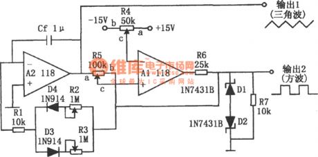
In the figure is the stable square wave and triangular wave generator. The characters of the circuit are that the frequencies of the square wave and triangular wave are nearly the same, the passive and positive amplitudes are symmetric; the positive and passive slopes of the triangular wave are not effected by the amplitude, and the slopes can be adjusted. Besides, the wave shape won't be changed when adjusting the basic LEV. The computing amplifier A2 is the integrator, which is driven by the output square waves. The amplitude of the square wave is fixed at ±5V by the Zener diodes of D1 and D2. (View)
View full Circuit Diagram | Comments | Reading(712)
The M50117F/AP/BP/CP oscillating connection circuit
Published:2011/6/18 2:53:00 Author:Seven | Keyword: oscillating, connection circuit
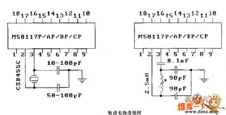
The oscillating connection circuit (View)
View full Circuit Diagram | Comments | Reading(454)
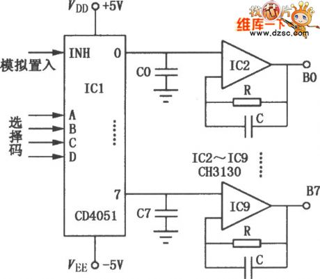
The CD4051 and CH3130 multi-channel demodulator circuit
Published:2011/6/18 2:55:00 Author:Seven | Keyword: multi-channel demodulator
View full Circuit Diagram | Comments | Reading(1525)
The S amplifier and encoding signal process logic circuit of the MC3373 infrared remote receiver
Published:2011/6/18 3:00:00 Author:Seven | Keyword: amplifier, encoding signal process, infrared remote receiver
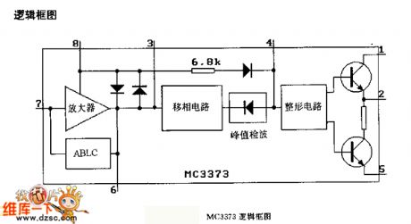
the logic frame diagram
MC3373 logic frame diagram (View)
View full Circuit Diagram | Comments | Reading(655)
The solar small lighting lamp circuit
Published:2011/6/18 3:01:00 Author:Seven | Keyword: solar, lighting lamp

View full Circuit Diagram | Comments | Reading(635)
The MC9482 (electronic toy) remote reception decoding logic frame circuit
Published:2011/6/19 0:29:00 Author:Seven | Keyword: remote reception, logic frame
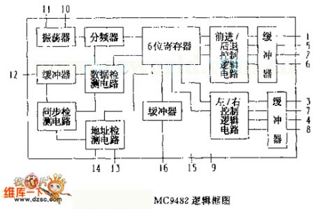
The MC9482 logic frame diagram (View)
View full Circuit Diagram | Comments | Reading(421)
The stable 5V output linear stabilizer circuit composed of MIC5158
Published:2011/6/14 11:22:00 Author:Borg | Keyword: output, linear stabilizer

View full Circuit Diagram | Comments | Reading(716)
The temperature range controller design circuit
Published:2011/6/18 3:03:00 Author:Seven | Keyword: temperature range, design circuit

View full Circuit Diagram | Comments | Reading(442)
The color circuit image of the fridge time delay protector
Published:2011/6/19 0:31:00 Author:Seven | Keyword: color circuit image, time delay protector

View full Circuit Diagram | Comments | Reading(416)
The dual-polarity symmetric stable power supply (LM7812 and LM7912)
Published:2011/6/14 11:17:00 Author:Borg | Keyword: dual-polarity, stable power supply

View full Circuit Diagram | Comments | Reading(7203)
| Pages:1724/2234 At 2017211722172317241725172617271728172917301731173217331734173517361737173817391740Under 20 |
Circuit Categories
power supply circuit
Amplifier Circuit
Basic Circuit
LED and Light Circuit
Sensor Circuit
Signal Processing
Electrical Equipment Circuit
Control Circuit
Remote Control Circuit
A/D-D/A Converter Circuit
Audio Circuit
Measuring and Test Circuit
Communication Circuit
Computer-Related Circuit
555 Circuit
Automotive Circuit
Repairing Circuit