
Circuit Diagram
Index 1738
ASK/FSK 450~300MHz Emitter Circuit Diagram
Published:2011/6/18 10:42:00 Author:Vicky | Keyword: ASK/FSK 450~300MHz

U27418 is a PLL emitter chip specially designed for meeting the low cost of data communication. The corresponding receiver chip is U3741.
Main technical features are listed as follows:
·Emitting frequency: 300~450 MHz;
·Modulation mode of ASK/FSK;
·Maximum transmission rate: 0 Kb/s;
·Voltage of power supply: 2.O~5.5 V;
·Maximum output power: 5 dBm(Vs=3 V,f=433.92 MHZ 9RPWRSET=1.2 kΩ);
·Maximum dissipation of power: 250 mW ;
·Maximum work current : l2.5 mA, maximum current of low-power mode: 0.35μA ;
·Microprocessor clock signal ,which can be compatible with microcontroller such as M44C090 and M44C890;
·ESD protection (excluding pins XT02 and XT01)as requested by MIL-STD.883(4KV HBM);
·Work temperature: -20~+70℃.
Applied circuit of U2741
(View)
View full Circuit Diagram | Comments | Reading(1653)
The basic UPS power supply principle circuit
Published:2011/6/21 6:26:00 Author:qqtang | Keyword: UPS, power supply

View full Circuit Diagram | Comments | Reading(1208)
The pulse accumulation counter circuit
Published:2011/6/21 6:24:00 Author:qqtang | Keyword: pulse, accumulation counter

In the figure is the example of the pulse accumulation counter circuit, which engages in pulse accumulative counting of A terminal, and it is used in the counting of input pulses. The S1~S4 are the reset switch, which are used to set the countered numbers. When the numbers are accumulated to the set values, the circuit is taking action, and the corresponding circuit of the relay control is taking action. If the time pulse in Figure 5-12 is added on A terminal, which can also compose a digital timing circuit base on the power supply frequency.
(View)
View full Circuit Diagram | Comments | Reading(851)
The single terminal flyback switch power supply circuit
Published:2011/6/21 6:58:00 Author:qqtang | Keyword: single terminal, flyback switch

The single terminal flyback switch power supply application circuit is shown in figure 3. The so-called single term means the magnet circuit side of the core in the high-frequency transformer. The so-called flyback means when the switch VT1 is conducting, the inductive voltage of primary coil in the high frequency transformer T is positive in the upper part by passive in the lower part, the rectifier diode VD1 is blocked and save power in the primary coil. When the switch pipe VT1 is blocked, the power stored by the primary coil is delivered to the load after it has been past the coil, rectified by VD1 and filtered by capacitor C.
(View)
View full Circuit Diagram | Comments | Reading(678)
The sound frequency noise generator principle circuit
Published:2011/6/21 6:28:00 Author:qqtang | Keyword: sound frequency, noise generator

View full Circuit Diagram | Comments | Reading(544)
The simple ore radio circuit
Published:2011/6/21 6:25:00 Author:qqtang | Keyword: ore radio

View full Circuit Diagram | Comments | Reading(2596)
The color TV remote control 21 circuit
Published:2011/6/21 2:05:00 Author:Seven | Keyword: color TV, remote control
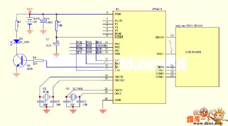
Figure: The color TV remote control 21 circuit (View)
View full Circuit Diagram | Comments | Reading(1079)
The simple but special regulated circuit
Published:2011/6/21 2:14:00 Author:Seven | Keyword: regulated circuit

The simple but special regulated circuit: In some conditions, if there needs a regulated circuit while it is running with load, as the control and detector, this circuit will seem brief and convenient. By adjusting the ratio of R1 and R2, the input voltage of the regulated module can be changed, the value of C1 is relative to the loading. A. If the single way thyristor is switched in to dual way thyristor, the circuit will be simpler. (View)
View full Circuit Diagram | Comments | Reading(661)
vehicle anti-theft device with ND vibration modules circuit
Published:2011/6/21 7:57:00 Author:John | Keyword: anti-theft device, vehicle, vibration module

Sensing part is the most advanced solid-state acceleration detection device, which have high detection sensitivity to vibration and have inhibit function to the surrounding environment’s noise signals. It is with strong anti-interference ability. The device contains dedicated control chip inside. And it is easy to use. It can be used for directly driving small power loads or a relay or alarm after being through amplification circuit. Therefore, it is widely used for anti-theft device in motor vehicles, safes, warehouse doors and windows and other occasions.
(View)
View full Circuit Diagram | Comments | Reading(668)
TV remote control 14 circuit
Published:2011/6/21 8:05:00 Author:John | Keyword: TV remote control

View full Circuit Diagram | Comments | Reading(638)
Thyristor energy consumption brake control circuit
Published:2011/6/21 8:03:00 Author:John | Keyword: Thyristor

Thyristor energy consumption brake control circuit is shown.
(View)
View full Circuit Diagram | Comments | Reading(1102)
TV remote control 09 circuit
Published:2011/6/21 9:07:00 Author:John | Keyword: TV remote control

View full Circuit Diagram | Comments | Reading(588)
TV remote control 10 circuit
Published:2011/6/21 9:05:00 Author:John | Keyword: TV remote control

View full Circuit Diagram | Comments | Reading(757)
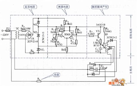
Thyristor furnace temperature automatic control circuit
Published:2011/6/21 8:08:00 Author:John | Keyword: Thyristor, furnace
View full Circuit Diagram | Comments | Reading(1278)
TV remote control 11 circuit
Published:2011/6/21 8:09:00 Author:John | Keyword: TV remote control

View full Circuit Diagram | Comments | Reading(561)
TV remote control 12 circuit
Published:2011/6/21 8:09:00 Author:John | Keyword: TV remote control

View full Circuit Diagram | Comments | Reading(546)
Motor starting circuit
Published:2011/6/21 8:10:00 Author:John | Keyword: Motor
View full Circuit Diagram | Comments | Reading(555)
Beijing Benz E320 engine control system circuit
Published:2011/6/21 8:11:00 Author:John | Keyword: engine

View full Circuit Diagram | Comments | Reading(1041)
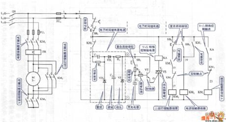
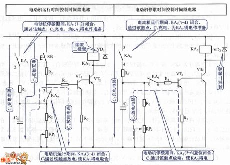
Motor intermittent start-stop cycling control circuit
Published:2011/6/21 8:13:00 Author:John | Keyword: Motor
View full Circuit Diagram | Comments | Reading(707)
TV remote control 13 circuit
Published:2011/6/21 8:06:00 Author:John | Keyword: TV remote control

View full Circuit Diagram | Comments | Reading(662)
| Pages:1738/2234 At 2017211722172317241725172617271728172917301731173217331734173517361737173817391740Under 20 |
Circuit Categories
power supply circuit
Amplifier Circuit
Basic Circuit
LED and Light Circuit
Sensor Circuit
Signal Processing
Electrical Equipment Circuit
Control Circuit
Remote Control Circuit
A/D-D/A Converter Circuit
Audio Circuit
Measuring and Test Circuit
Communication Circuit
Computer-Related Circuit
555 Circuit
Automotive Circuit
Repairing Circuit