Circuit Diagram
Index 1725
The electronic valve difference common-gate phase-reversing circuit
Published:2011/6/20 22:01:00 Author:Seven | Keyword: electronic valve, common-gate

The electronic valve difference common-gate phase-reversing circuit is shown in theabove figure.
(View)
View full Circuit Diagram | Comments | Reading(919)
The sawtooth wave signal generator composed of DAC08EQ
Published:2011/6/14 4:16:00 Author:Borg | Keyword: sawtooth wave, signal generator
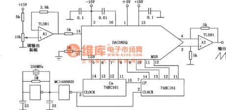
The sawtooth wave signal generator, which consists of DAC08EQ, is simply constructed, and the signal waveform of the generator is highly precise, the generator is used in highly precise signal waveform circuits or instruments. See as the figure. (View)
View full Circuit Diagram | Comments | Reading(585)
The over-voltage auto power-down equipment setting circuit
Published:2011/6/19 0:49:00 Author:Seven | Keyword: over-voltage, power-down

The 220V mains provide with a stable 12V working voltage through C1, VD1 and DW1, and VD3, R2 and RP1 compose a voltage distributing sampling circuit. When the mains voltage is normal, DW2 is blocked, the working voltage on 5-pin of TWH8778 is lower than 1.6V, the relay J is open, the mains provides power normally after crossing the J-1 commonly closed touch spot; when the mains voltage is high than the normal value, DW2 is breakdown and conducting, LEV on 5-pin of TWH8778 is rising to 1.6v, which reverses IC, and the 3-pin outputs a high LEV, the relay is closed and the power supply of the electric apparatus is cut off immediately. (View)
View full Circuit Diagram | Comments | Reading(825)
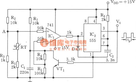
The temperature/pulse width converter circuit of 555
Published:2011/6/13 23:38:00 Author:Borg | Keyword: temperature/pulse width converter
View full Circuit Diagram | Comments | Reading(780)
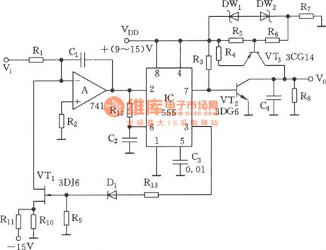
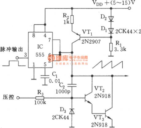
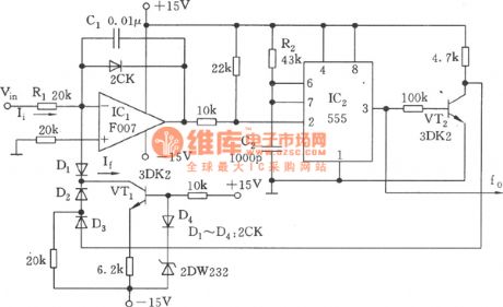
The voltage/frequency converter circuit of linear sawtooth wave (555)
Published:2011/6/13 23:37:00 Author:Borg | Keyword: voltage/frequency converter, linear sawtooth wave
View full Circuit Diagram | Comments | Reading(815)
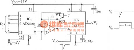
The digit/time converter circuit of 555
Published:2011/6/13 23:35:00 Author:Borg | Keyword: digit/time converter
View full Circuit Diagram | Comments | Reading(662)
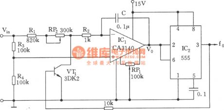
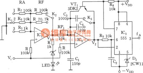
The linear voltage/frequency converter circuit (555)
Published:2011/6/13 21:22:00 Author:Borg | Keyword: voltage/frequency converter


frequency-voltage converting relationship:
(View)
View full Circuit Diagram | Comments | Reading(3202)
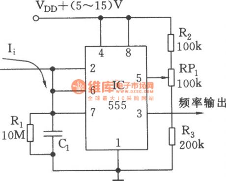
The simple current/frequency converter (555)
Published:2011/6/13 21:19:00 Author:Borg | Keyword: current/frequency converter
View full Circuit Diagram | Comments | Reading(1474)
The voltage/frequency converter of low switching parameter (555)
Published:2011/6/13 21:18:00 Author:Borg | Keyword: voltage/frequency converter, switching parameter
View full Circuit Diagram | Comments | Reading(542)
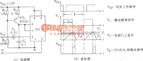
The simple voltage/pulse width converter (555)
Published:2011/6/13 21:15:00 Author:Borg | Keyword: voltage, pulse width, converter
View full Circuit Diagram | Comments | Reading(616)
The triode voltage steady circuit
Published:2011/6/19 1:02:00 Author:Seven | Keyword: voltage steady circuit

The input voltage of the emitter output circuit is fixed at VZ, so the output voltage VO=VZ-VBE is also fixed. When the grid voltage is fluctuating, as VZ is almost still and VO is the same, the change of VI is adjusted by VCE, so the triode is called the adjusting pipe. When RL changes and it causes the fluctuation of IO, as lone as the △IZ is in the normal range of the stabilovolt tube, VZ will remains the same, i.e VO is almost stable.
The fluctuation of the circuit output current can be expanded to (1+β)△IZ, so it is also called the enlarging voltage stable diode circuit. (View)
View full Circuit Diagram | Comments | Reading(582)
The adjustable symmetric triangular wave generator circuit (555)
Published:2011/6/13 21:06:00 Author:Borg | Keyword: adjustable, symmetric triangular wave
View full Circuit Diagram | Comments | Reading(884)
The efficient step-up stable power supply consisting of MAX632
Published:2011/6/14 20:46:00 Author:Borg | Keyword: step-up, power supply
View full Circuit Diagram | Comments | Reading(610)
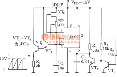
The linear sawtooth wave generator circuit of 555
Published:2011/6/13 21:01:00 Author:Borg | Keyword: linear sawtooth wave
View full Circuit Diagram | Comments | Reading(1843)
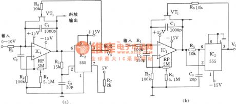
The linear voltage/frequency converter circuit of 555 (4)
Published:2011/6/13 23:34:00 Author:Borg | Keyword: voltage/frequency converter
View full Circuit Diagram | Comments | Reading(863)
The machine tool magnetic sucker low-current protection circuit
Published:2011/6/19 2:47:00 Author:Seven | Keyword: machine tool, magnetic sucker, low-current


See as the circuit, the +24V is generated by stepping down the 110V power supply. When the touch spot JK of the magnetic sucker circuit is closed, the sucker is on and working, whose regulated current is 1.4A(the current of strong sucker is higher). At the moment, the sampling resistor which is serially connected in the electric sucker will have a 1.4v voltage drop, the dropped voltage is sampled by the potentiometer RP1 and imposed on the transistor VT1 input circuit, and then compound-magnified by VT1 and VT2. The multiple after being compounded by VT1 and VT2 is high.
(View)
View full Circuit Diagram | Comments | Reading(1046)
The linear voltage/frequency converter circuit of 555 (2)
Published:2011/6/13 23:32:00 Author:Borg | Keyword: voltage/frequency converter
View full Circuit Diagram | Comments | Reading(432)
The linear voltage/frequency converter circuit of 555 (3)
Published:2011/6/13 23:33:00 Author:Borg | Keyword: voltage/frequency converter
View full Circuit Diagram | Comments | Reading(566)
The linear voltage/frequency converter of 555 (1)
Published:2011/6/13 23:31:00 Author:Borg | Keyword: voltage/frequency converter
View full Circuit Diagram | Comments | Reading(1402)
The sawtooth scanning voltage circuit with good linearity
Published:2011/6/13 20:55:00 Author:Borg | Keyword: sawtooth scanning voltage, linearity
View full Circuit Diagram | Comments | Reading(483)
| Pages:1725/2234 At 2017211722172317241725172617271728172917301731173217331734173517361737173817391740Under 20 |
Circuit Categories
power supply circuit
Amplifier Circuit
Basic Circuit
LED and Light Circuit
Sensor Circuit
Signal Processing
Electrical Equipment Circuit
Control Circuit
Remote Control Circuit
A/D-D/A Converter Circuit
Audio Circuit
Measuring and Test Circuit
Communication Circuit
Computer-Related Circuit
555 Circuit
Automotive Circuit
Repairing Circuit
