
Circuit Diagram
Index 1732
Servo motor speed control circuit
Published:2011/6/22 19:15:00 Author:TaoXi | Keyword: Servo motor, speed, control circuit

The servo motor speed control circuit connects the photoelectric encoder with the motor shaft, the LED is the indicator light of the PLL detection, it turns on when the control circuit is synchronous. The PLL is the phase synchronous control method of the electrical moter, it uses the chip of TC9142.
(View)
View full Circuit Diagram | Comments | Reading(4346)
Pulse generator circuit uses the interrupt beam
Published:2011/6/22 3:47:00 Author:TaoXi | Keyword: Pulse generator, interrupt beam
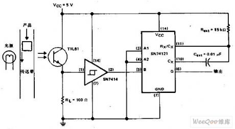
When the object on the band carrier keeps out the light, this circuit will output a pulse. The light source makes the photoelectric transistor to keep in the conduction state. This will produce a high logic level voltage on the Schmitt inverter, and it also produces the low logic level voltage on the pin-5 of the monostable circuit which is compatible with the TTL. When the object keeps out the light, the TIL81 turns off the Schmitt inverter to trigger the monostable circuit.
(View)
View full Circuit Diagram | Comments | Reading(608)
Receiver circuit used with the 50kHz FM transmitter
Published:2011/6/22 18:55:00 Author:TaoXi | Keyword: Receiver, circuit, 50kHz, FM, transmitter
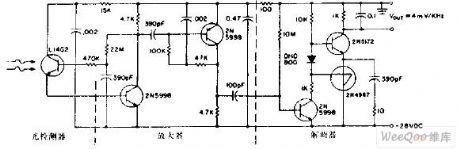
This circuit is composed of a L14G2 detector, the two stages amplifier and a frequency modem, it can be used in the multi-level amplifier which has the automatic gain control to get high sensitivity.
(View)
View full Circuit Diagram | Comments | Reading(1044)
Three-phase AC electric welder no-load automatic stop control circuit
Published:2011/6/22 19:09:00 Author:TaoXi | Keyword: Three-phase, AC, electric welder, no-load, automatic stop, control circuit

The circuit is as shown in the figure. The subprime coil clamp line port of the electric welder's transformer is connected with the landline through the welding rod to form the short circuit, the relay ZJ releases. The normally closed contact point ZJ2 closes to make the AC contactor CJ to close, and it locks itself through the normally open contact point CJ1, the major loop is connected, the electric welder's transformer produces the normal voltage and current, so you can do the welding work.
After the welding stops, because the open-circuit (composed of the clamp line port and the landline port) voltage increases, so the relay ZJ gets power to close through the AC contactor's normally open contact point CJ4.
(View)
View full Circuit Diagram | Comments | Reading(751)
Temperature sensor A/D converter circuit
Published:2011/6/22 20:56:00 Author:TaoXi | Keyword: Temperature sensor, A/D, converter

In the microcontroller temperature measurement system, you need to change the analog quantity of the AD592 into the digital quantity through the A/D converter, then the digital quantity is sent to the single-chip microcomputer to be processed. The A/D converter circuit of the AD592 is as shown in the figure, this circuit uses the AD670 for the 8-bit A/D conversion. The AD670 belongs to the 4-port differential input, it is designed as the 8-bit A/D converter which is composed of the input attenuator, the measurement amplifier and the reference voltage source. The four analog input ports are divided into two groups, every group has the attenuator which is composed of the 1kΩ and 10kΩ resistance.
(View)
View full Circuit Diagram | Comments | Reading(1399)
Temperature compensation circuit composed of the piezoresistive pressure sensor
Published:2011/6/22 21:13:00 Author:TaoXi | Keyword: Temperature, compensation circuit, piezoresistive, pressure sensor
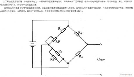
In order to solve the problem of temperature drift, you usually use the constant current source power supply mode. But because the reasons of production process.etc, the resistances of the bridge are not the same, they have the zero position output. So even we use the constant current source power supply mode, there will still be a certain temperature error.
The piezoresistive pressure sensor has the temperature drift phenomena, and the sensitivity changes with the temperature. You can use add the thermistor in the bridge circuit to solve the zero drift of the pressure sensor. As the figure shows, the RT is the thermistor which is mainly used to compensate for the zero drift; the RP can be used to adjust the zero position output.
(View)
View full Circuit Diagram | Comments | Reading(1731)
Digital tachometer circuit based on the magnetic sensor
Published:2011/6/22 21:30:00 Author:TaoXi | Keyword: Digital tachometer, magnetic sensor

The digital tachometer circuit is as shown in the figure. It is composed of the disk with the permanent magnet, the Hall integrated sensor, the selective passing gate circuit, the time base signal circuit, the power count circuit and the digital display circuit. The count circuit and the digital display circuits use the CMOS-LED digital display component CLlO2, it can count and display the numerical code.
The input shaft of the turntable is connected with the measured rotating shaft, when the measured rotating shaft is rotating, it will drive the turntable to turn with it. When the small permanent magnet of the turntable is getting through the Hall integrated sensor IC1, IC1 will change the magnetic signal into the speed electric signal. This signal reverse-phase inputs to the input port of the NAND gate 3 through the NOT gate l. (View)
View full Circuit Diagram | Comments | Reading(5498)
Cell phone battery charging circuit with the discharge function
Published:2011/6/22 21:50:00 Author:TaoXi | Keyword: Cell phone, battery, charging circuit, discharge function

1. Circuit and working principle:
The cell phone Lithium battery charge principle with the discharge function is as shown in the figure, the circuit structure can be divided into two parts:
(1) The discharger circuit is composed of the operational amplifiers A1-A4, the voltage regulator IC1 and the transistor BG1. The discharger core circuit is composed of the R-S flip-flop to control the conduction and on-off of the discharge tube BG1.
(2) The charging circuit is composed of the DC/DC buck type switching voltage regulator, it outputs the 4.2V voltage.
2. Component selection:
The IC1 uses the TL431, it is in the TO-92 package; the IC2 uses the MC34063, it is in the 8-pin dual-row DIP package; the A1-A4 use the LM324.
(View)
View full Circuit Diagram | Comments | Reading(1729)
1-9V regulated power supply digital display circuit
Published:2011/6/22 22:04:00 Author:TaoXi | Keyword: 1-9V, regulated, power supply, digital display


The adjustable regulated power supply which is made by the LM317 is common, the 1-9V regulated power supply additional device is as shown in the figure. This regulated power supply can output the DC 1~9V according to the need, and it chooses the red LED digital tube to display the output voltage of 1~9.
The LED digital tube 7-segment display codes are as shown in the table, the coding is finished by the S1 abd VD5~VD17 (in the table, 1 means light, 0 means extinguishing. S1 and S2 can use the band switch to restructure, the circuit is simple, with the connection method of the figure, you can do it by yourself.
(View)
View full Circuit Diagram | Comments | Reading(1381)
Simple nickel-cadmium battery charging circuit composed of three components
Published:2011/6/23 1:06:00 Author:TaoXi | Keyword: Simple, nickel-cadmium battery, charging circuit, three components

The charger of the figure is composed of three components, it is the simplest charger, this circuit is the capacitor current limiting charging circuit, the charging current is decided by the current limiting capacitance C, both the charging of one battery or more than a dozen batteries, the charge current will not change, D1 and D2 are the rectifier diodes, the current limiting capacitance need to choose the >400V non-polarity capacitor, the charge current should not exceed 100mA, if you want to charge the 500mAh number five nickel cadmium battery, the charging time is about 6 hours.
(View)
View full Circuit Diagram | Comments | Reading(2579)
6V power supply emergency light automatic charging and discharging circuit
Published:2011/6/23 1:19:00 Author:TaoXi | Keyword: 6V, power supply, emergency light, automatic, charging, discharging

The circuit and working principle of the emergency light: the 6V power supply supplies the reference voltage for the base electrode T1, the relay J realizes the self-locking and automatic power-off of the switch K, when you connect the battery and press K, the power indicator light L turns on, and J closes, the K is locked by its contact point J-0, the charging begins, at this time the battery owes the electricity, so the emitter voltage of T1 is lower than (7.5V+0.65V), T1 and T2 cut off, they have no effect on T3. When the battery voltage is charged to 735V, the emitter voltage of T1 is 7.5V+0.65V, so T1 and T2 conduct, T3 cuts off because the base electrode voltage decreases, J releases and J-0 cuts off, the charging stops.
(View)
View full Circuit Diagram | Comments | Reading(1338)
Micro switch power supply charger circuit
Published:2011/6/23 1:22:00 Author:TaoXi | Keyword: Micro, switch, power supply, charger circuit

Micro switch power supply charger circuit (View)
View full Circuit Diagram | Comments | Reading(2300)
Nokia mobile phone travel charger circuit
Published:2011/6/23 1:29:00 Author:TaoXi | Keyword: Nokia, mobile phone, travel charger

The Nokia 8210 mobile phone travel charger circuit is produced in ShangHai, the shell is labeled with: Input AC220V/50Hz(<=30mA), output 4.2V(<=200mA). In the use of charging, for the lithium battery which needs to be charged, when the voltage of the lithium battery is charged to 3.98V, the red light of the charger circuit turns off, the green light turns on. The charging time is about four hours. The author analyzes the charger and draws the circuit for reader's use and reference, the op-amp IC in this circuit is used as the comparator.
(View)
View full Circuit Diagram | Comments | Reading(1857)
12V/24V lead-acid battery charging circuit
Published:2011/6/23 1:35:00 Author:TaoXi | Keyword: 12V/24V, lead-acid battery, charging circuit

The LM339 simple lead-acid battery charging circuit is as shown in the figure, you can use two 24V lead-acid batteries as the power supply.
(View)
View full Circuit Diagram | Comments | Reading(5939)
Simple servo motor drive control circuit
Published:2011/6/23 2:07:00 Author:TaoXi | Keyword: Simple, servo motor, drive control
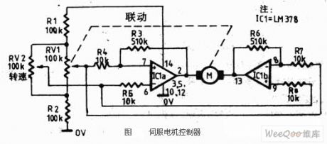
The servo motor is designed as one kind of traditional motor. It is the execution component of the automatic device. The most important feature of the servo motor is the controllable feature. When there is the control signal the servo motor turns, and the speed is proportional to the control voltage. If you remove the control voltage, the servo motor will immediately stop turning. The servo motor can be used in wide range of applications such as all of the automatic control system and the household electrical appliances (CD players, video players).
Figure: The simple servo motor drive control circuit (View)
View full Circuit Diagram | Comments | Reading(4772)
Audio power amplifier stage with LM-386 circuit
Published:2011/6/16 6:08:00 Author:John | Keyword: Audio power amplifier stage

Figure shows the design based on LM-386. It is the LM-386 low-power audio level’s single-ended output configuration. This IC includes a pre-amplifier and power amplifier with the nominal output power of 250mW. LM-386 series audio power IC is simple, but high gain is needed. If it is with unreasonable configuration or if the ground is not properly configured, it may cause self-oscillation.
figure: Audio power amplifier stage with LM-386 circuit (View)
View full Circuit Diagram | Comments | Reading(1438)
Mazda 95TAURUS rear wiper washer circuit
Published:2011/6/21 0:40:00 Author:John | Keyword: rear wiper washer
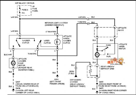
Mazda 95TAURUS rear wiper washer circuitis shown.
(View)
View full Circuit Diagram | Comments | Reading(589)
Mazda 95TAURUS electric rearview mirror circuit
Published:2011/6/21 0:39:00 Author:John | Keyword: electric rearview mirror
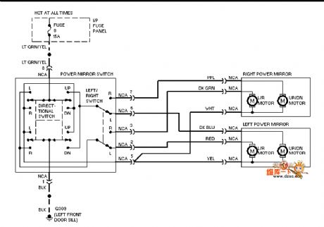
Mazda 95TAURUS electric rearview mirror circuit is shown.
(View)
View full Circuit Diagram | Comments | Reading(620)
Mazda 95TAURUS remote door lock circuit
Published:2011/6/21 0:39:00 Author:John | Keyword: remote door lock
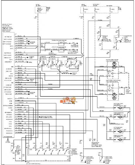
Mazda 95TAURUS remote door lock circuit is shown.
(View)
View full Circuit Diagram | Comments | Reading(581)
Mazda 95TAURUS (3.8L) starting circuit
Published:2011/6/21 0:39:00 Author:John
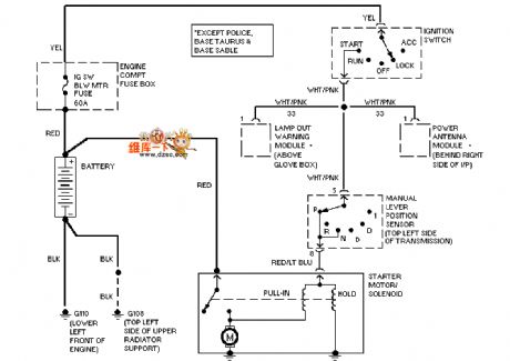
Mazda 95TAURUS (3.8L) starting circuit is shown.
(View)
View full Circuit Diagram | Comments | Reading(578)
| Pages:1732/2234 At 2017211722172317241725172617271728172917301731173217331734173517361737173817391740Under 20 |
Circuit Categories
power supply circuit
Amplifier Circuit
Basic Circuit
LED and Light Circuit
Sensor Circuit
Signal Processing
Electrical Equipment Circuit
Control Circuit
Remote Control Circuit
A/D-D/A Converter Circuit
Audio Circuit
Measuring and Test Circuit
Communication Circuit
Computer-Related Circuit
555 Circuit
Automotive Circuit
Repairing Circuit