
Circuit Diagram
Index 1733
Mazda 95TAURUS (without DRL) headlights and fog lights circuit
Published:2011/6/21 0:39:00 Author:John | Keyword: headlight, fog light
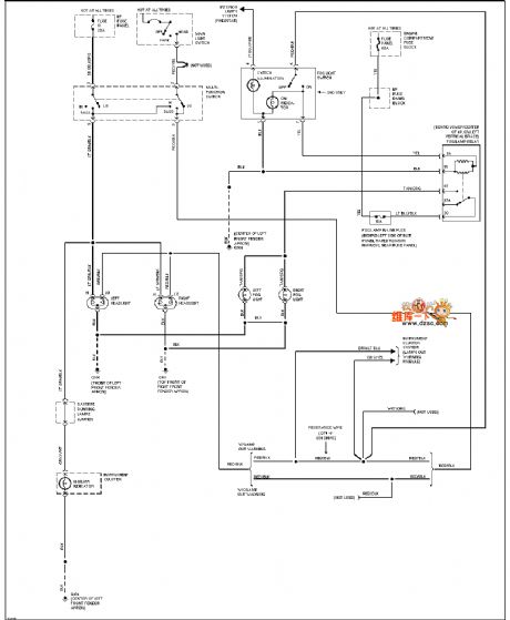
Mazda 95TAURUS (without DRL) headlights and fog lights circuitis shown. (View)
View full Circuit Diagram | Comments | Reading(734)
High-pass filter circuit
Published:2011/6/20 5:57:00 Author:John | Keyword: High-pass filter
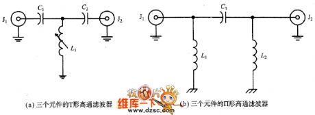
High-pass filter (HPF) cuts off signal frequency which is below -3dB cutoff frequency and allows for signal frequency which is above the cutoff frequency.
Figure (a) and Figure (b) show single high-pass filters. These are inversions of LPF single low-pass filters. Capacitance is placed in series in the signal path but the inductance is placed in parallel in the signal channel. The model shown in the figure (a) is T-shaped structure that shown in the figure (b) is Ⅱtype filter.
(View)
View full Circuit Diagram | Comments | Reading(718)
Mazda 94THUNDERBIRD airbag circuit
Published:2011/6/21 0:28:00 Author:John | Keyword: airbag

Mazda 94THUNDERBIRD airbag circuit is shown.
(View)
View full Circuit Diagram | Comments | Reading(644)
Mazda 94THUNDERBIRD electric antenna circuit
Published:2011/6/21 0:28:00 Author:John | Keyword: electric antenna
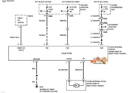
Mazda 94THUNDERBIRD electric antenna circuit is shown.
(View)
View full Circuit Diagram | Comments | Reading(663)
MOSFET active preselector circuit
Published:2011/6/21 0:27:00 Author:John | Keyword: active preselector

MOSFET active preselector circuit is shown.
(View)
View full Circuit Diagram | Comments | Reading(3773)
varactor diode adjusting MOSFET active preselector circuit
Published:2011/6/21 0:27:00 Author:John | Keyword: varactor diode, MOSFET active preselector

Varactor diode adjusting MOSFET active preselector circuit is shown.
(View)
View full Circuit Diagram | Comments | Reading(2334)
MOSFET variable RF gain control circuit
Published:2011/6/16 11:46:00 Author:John | Keyword: variable RF
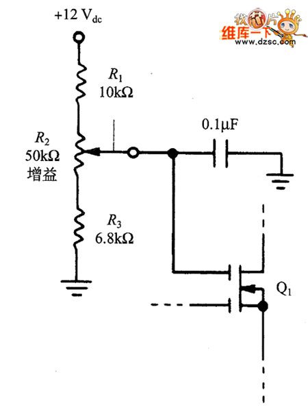
]In the two kinds of MOSFET circuits, the fixed bias network is used to set the gate G2 with a positive DC voltage. It can be replaced with a variable voltage circuit, just as shown in the figure. The potentiometer in the figure can be used as RF gain control device, in order to reduce the gain impact on the strong signal and increase the gain on the weak signal. This design allows the active shunts to prevent strong signal form overloading.
figure: MOSFET variable RF gain control circuit (View)
View full Circuit Diagram | Comments | Reading(884)
The electronic rodent repeller circuit diagram 2
Published:2011/6/14 20:31:00 Author:Lucas | Keyword: Electronic rodent repeller

The electronic rodent repeller circuit is relatively simple, it is composed of 5 times pressure rectifier circuit (rectifier diodes VD1 ~ VD5 and capacitors C1 ~ C5) and labyrinth electrodes, and the circuit is shown as the chart. AC 220Y voltage is rectified and filtered by rectifier diode VD1 ~ VD5 and capacitors C1 ~ C5 to produce a pulse DC high voltage with about 1.5kV, which is added on the 220V voltage ends of labyrinth electrodes, when the rat steps on the electrode, the current passes the rat, the mouse will die as electric shock. R uses 1/2W metal film resistor. C1 ~ C5 select ceramic capacitors with the voltage in 600V. VD1 ~ VD5 use 1N4007 silicon rectifier diodes.
(View)
View full Circuit Diagram | Comments | Reading(1912)
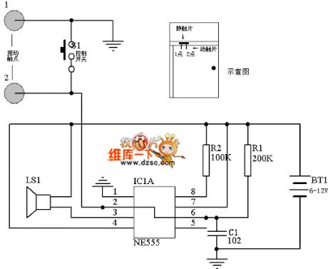
Broken line alarm production circuit diagram
Published:2011/6/14 3:46:00 Author:Lucas | Keyword: Broken line , alarm, production
View full Circuit Diagram | Comments | Reading(643)
BG602 charger circuit
Published:2011/6/16 22:14:00 Author:chopper | Keyword: charger circuit

View full Circuit Diagram | Comments | Reading(795)
A3 norm power supply circuit
Published:2011/6/14 8:24:00 Author:chopper | Keyword: power supply

View full Circuit Diagram | Comments | Reading(700)
The 200MHz cascode amplifier circuit principle diagram
Published:2011/6/20 21:54:00 Author:Seven | Keyword: cascode, amplifier circuit

The 200MHz cascode amplifier circuit principle diagram is shown in the above figure.
AGC range:59dB; power gain:17dB;L1=0.07 μH central head; L2=0.07 μH the plug is at the 1/4 point from the earth terminal (View)
View full Circuit Diagram | Comments | Reading(1337)
The PLL FM demodulator (LM565CN、RC4558DN) circuit
Published:2011/6/16 20:48:00 Author:qqtang | Keyword: FM demodulator
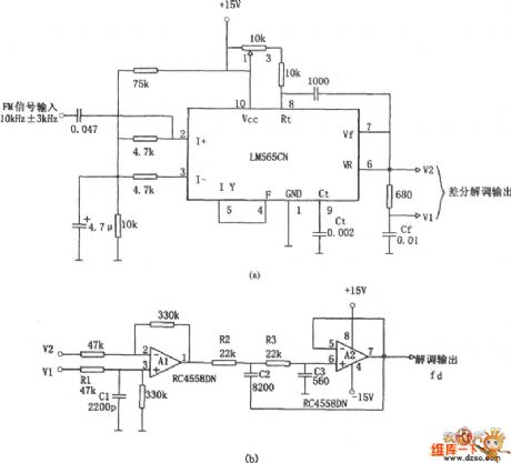
In the figure is a 10kHz±3kHz FM demodulator circuit consisting of LM565CN. The differential demodulation of V1 and V2 is level-shifted and amplified by A1 difference amplifier in figure (b), then the 20KHz pulse impulse momentum is removed by LPF composed of A2.
(View)
View full Circuit Diagram | Comments | Reading(2785)
The bilateral band modem circuit composed of NE561B
Published:2011/6/16 20:55:00 Author:qqtang | Keyword: bilateral band, modem circuit

In the figure is the bilateral band modem circuit composed of NE561B. The loading frequency of the input modulating signal is f0=1MHz. When the AM modulation signal is added on the input terminal of the multiplier, it is also added on the phase detection circuit by Rv1, CY1, Y2 and CY2, and it sets the VCO frequency of PLL at f0.
(View)
View full Circuit Diagram | Comments | Reading(1752)
The STK4161 application circuit
Published:2011/6/20 1:01:00 Author:Seven | Keyword: application circuit

The STK4161 application circuit is shown in the following circuit.
(View)
View full Circuit Diagram | Comments | Reading(2149)
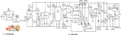
The practical ultrasonic wave remote control reception circuit
Published:2011/6/20 22:06:00 Author:Seven | Keyword: ultrasonic wave, remote control
The practical ultrasonic wave remote control reception circuit is shown in the figure.
(View)
View full Circuit Diagram | Comments | Reading(1047)
The electric energy-saving lamp circuit
Published:2011/6/20 0:39:00 Author:Seven | Keyword: energy-saving lamp

View full Circuit Diagram | Comments | Reading(3212)
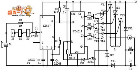
The infrared remote control music outlet circuit
Published:2011/6/20 0:40:00 Author:Seven | Keyword: infrared, remote control
The infrared remote control music outlet circuit is shown in the figure.
(View)
View full Circuit Diagram | Comments | Reading(903)
The light touch switch circuit
Published:2011/6/20 0:44:00 Author:Seven | Keyword: switch circuit

View full Circuit Diagram | Comments | Reading(621)
The single key switch circuit (2)
Published:2011/6/20 0:48:00 Author:Seven | Keyword: key switch

View full Circuit Diagram | Comments | Reading(995)
| Pages:1733/2234 At 2017211722172317241725172617271728172917301731173217331734173517361737173817391740Under 20 |
Circuit Categories
power supply circuit
Amplifier Circuit
Basic Circuit
LED and Light Circuit
Sensor Circuit
Signal Processing
Electrical Equipment Circuit
Control Circuit
Remote Control Circuit
A/D-D/A Converter Circuit
Audio Circuit
Measuring and Test Circuit
Communication Circuit
Computer-Related Circuit
555 Circuit
Automotive Circuit
Repairing Circuit