
Circuit Diagram
Index 1736
The STK1040 application circuit
Published:2011/6/20 22:20:00 Author:Seven | Keyword: application circuit

The STK1040 application circuit is shown as above.
(View)
View full Circuit Diagram | Comments | Reading(1074)
The light dependent control circuit
Published:2011/6/20 22:21:00 Author:Seven | Keyword: light dependent, control circuit

When one of the warps is broken, the light barrier which was hold by the warp is falling and blocks the light source of the LDR 3DU21, then the relay circuit is released, which controls the pulling over of the motor. The circuit is shown in the figure. (View)
View full Circuit Diagram | Comments | Reading(569)
The stereo sound volume remote control circuit
Published:2011/6/20 11:48:00 Author:Seven | Keyword: stereo sound volume, remote control

The stereo sound volume remote control circuit is shown as follows:
(View)
View full Circuit Diagram | Comments | Reading(694)
The SBX1483—11/12/51/52 typical application circuit
Published:2011/6/20 11:51:00 Author:Seven | Keyword: typical application circuit
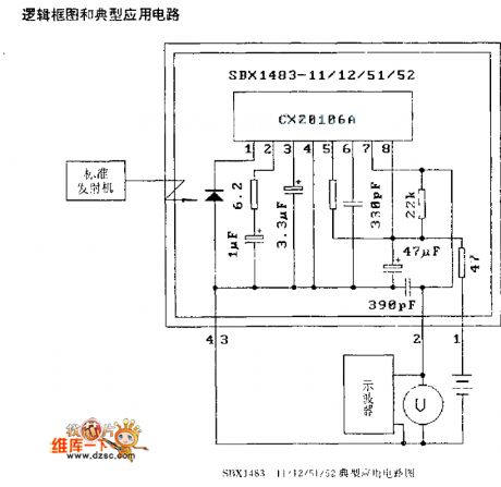
Figure: The SBX1483—11/12/51/52 typical application circuit (View)
View full Circuit Diagram | Comments | Reading(996)
The BA532 audio power amplifier circuit
Published:2011/6/20 20:52:00 Author:Seven | Keyword: audio power amplifier

BA532 is a low-frequency power amplifier circuit which is used in OTL circuits, its output power is 5.8w, and there is the loading short, over-voltage and over-heat protection circuit, the circuit is in 10-pin package, the features of the circuit are: When the voltage of the power supply is 13.8v, the loading impedance is 8Ω, when the THD=10%, the output power may reach 5.8w, the wave rejection ratio is 40dB, the pin is the same with BA511A and BA521. The circuit is often used in vehicle stereo cassette players, radios, TV sets and cassette recorder as the power output circuit.
(View)
View full Circuit Diagram | Comments | Reading(2680)
The 6sn7 classic wiring circuit
Published:2011/6/20 22:25:00 Author:Seven | Keyword: classic wiring circuit

The 6sn7 classic wiring circuit is shown as above. (View)
View full Circuit Diagram | Comments | Reading(1143)
The FU-50 single terminal circuit
Published:2011/6/20 22:40:00 Author:Seven | Keyword: single terminal

The FU-50 single terminal circuit is shown as above. (View)
View full Circuit Diagram | Comments | Reading(2954)
The FU29 push-pull circuit
Published:2011/6/20 22:41:00 Author:Seven | Keyword: push-pull circuit

The FU29 push-pull circuit is shown as above. (View)
View full Circuit Diagram | Comments | Reading(3756)
The TA7657P typical application circuit
Published:2011/6/20 22:42:00 Author:Seven | Keyword: typical application circuit
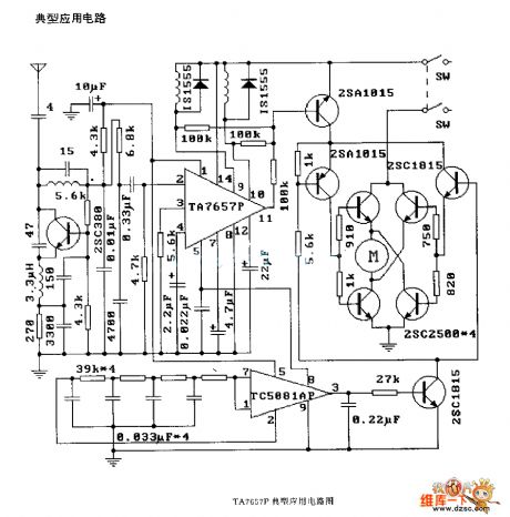
Figure: The TA7657P typical application circuit (View)
View full Circuit Diagram | Comments | Reading(668)
The TA814lS typical application circuit
Published:2011/6/20 22:44:00 Author:Seven | Keyword: typical application circuit

The TA814lS typical application circuit (View)
View full Circuit Diagram | Comments | Reading(477)
The TDA3048 typical application circuit
Published:2011/6/20 22:43:00 Author:Seven | Keyword: typical application circuit
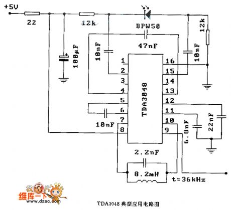
Figure: The TDA3048 typical application circuit (View)
View full Circuit Diagram | Comments | Reading(805)
The 6N11+6N5 headphone amplifier circuit
Published:2011/6/21 2:07:00 Author:Seven | Keyword: headphone amplifier

The 6N11+6N5 headphone amplifier circuit is shown as above. (View)
View full Circuit Diagram | Comments | Reading(2823)
The YN 5203 typical application circuit
Published:2011/6/21 1:40:00 Author:Seven | Keyword: typical application circuit
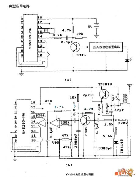
The YN 5203 typical application circuit (View)
View full Circuit Diagram | Comments | Reading(778)
The full-bile rectifier regulated circuit
Published:2011/6/21 1:53:00 Author:Seven | Keyword: full-bile, rectifier

The full-bile rectifier regulated circuit is shown as above.
(View)
View full Circuit Diagram | Comments | Reading(580)
The wide band linear detection circuit of 10MHz
Published:2011/6/16 20:13:00 Author:qqtang | Keyword: wide band, linear detection circuit

In the figure is the wide band linear detection circuit of 10MHz, which is used in measuring instruments like millivoltmeters. The computing amplifier is fixed with a wide band μPC53, whose output is amplified by the differential amplifier composed of the triode 2SC384. The diode in the circuit is Ge diode, by installing it in the backward feedback circuit, the power supply voltage is increased by the differential circuit.
(View)
View full Circuit Diagram | Comments | Reading(671)
The 50Hz time based signal generator circuit
Published:2011/6/19 20:07:00 Author:qqtang | Keyword: time based, signal generator
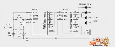
View full Circuit Diagram | Comments | Reading(734)
The power supply over current protection circuit of the ring switch
Published:2011/6/16 20:16:00 Author:qqtang | Keyword: power supply, protection circuit

The power supply over current protection circuit of the ring switch is shown in the following circuit:
(View)
View full Circuit Diagram | Comments | Reading(695)
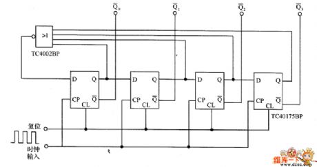
The decimal additive counter circuit
Published:2011/6/21 6:14:00 Author:qqtang | Keyword: decimal, additive counter
In the figure is an example of the decimal additive counter circuit, which splits the input frequency in the decimal method, so it is called the decimal counter, and this is also the basic form of digital counters.
(View)
View full Circuit Diagram | Comments | Reading(521)
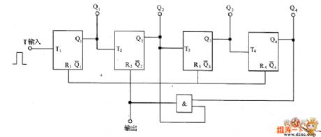
The ring formed counter circuit
Published:2011/6/21 6:08:00 Author:qqtang | Keyword: ring formed, counter
In the circuit is an example of the ring formed counter circuit, the period of the circuit is 4 hours, and the circuit is widely used in all kinds of counter circuit.
(View)
View full Circuit Diagram | Comments | Reading(548)
The instrument board lighting circuit
Published:2011/6/21 6:10:00 Author:qqtang | Keyword: instrument board, lighting circuit

The instrument board lighting circuit is shown as above.
(View)
View full Circuit Diagram | Comments | Reading(629)
| Pages:1736/2234 At 2017211722172317241725172617271728172917301731173217331734173517361737173817391740Under 20 |
Circuit Categories
power supply circuit
Amplifier Circuit
Basic Circuit
LED and Light Circuit
Sensor Circuit
Signal Processing
Electrical Equipment Circuit
Control Circuit
Remote Control Circuit
A/D-D/A Converter Circuit
Audio Circuit
Measuring and Test Circuit
Communication Circuit
Computer-Related Circuit
555 Circuit
Automotive Circuit
Repairing Circuit