
Circuit Diagram
Index 1730
The single terminal forward switch power supply circuit
Published:2011/6/23 1:51:00 Author:qqtang | Keyword: single terminal, forward, switch power supply

The single terminal forward switch power supply circuit is shown in the figure. This circuit is like the backward switch power supply circuit in terms, but the working condition is different. When the switch VT1 is conducting, VD2 is also conducting, at the moment, the grid is sending energy to the loading, the filter inductor L is storing energy; when the switch VT1 is blocked, the inductor L is releasing power to the loading by the freewheel diode VD3.
In the circuit, there is also a clamper coil and diode VD2, which can keep the maximum voltage of the VT1 within the twice of the power supply voltage. (View)
View full Circuit Diagram | Comments | Reading(758)
The principle circuit of the switch regulated power supply
Published:2011/6/23 1:41:00 Author:qqtang | Keyword: principle circuit, regulated power supply

The principle circuit of the switch regulated power supply is shown in the figure.After the AC voltage is past the rectifier circuit and the filter circuit, it becomes a DC voltage which contains some impulse, the voltage flows into the high frequency converter and is turned into a wave square of needed voltage, finally, the square wave is rectified and becomes a needed DC voltage.The control circuit is a pulse width modulator, which mainly consists of sub-circuits of the sampler, the oscillator, the pulse width modulator and the reference voltage, etc. (View)
View full Circuit Diagram | Comments | Reading(634)
The FM demodulation circuit
Published:2011/6/20 9:39:00 Author:Seven | Keyword: FM demodulation
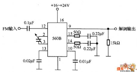
In the figure is the FM demodulation circuit instance, which converts the FM central frequency(10.7 MHz) into the low-frequency signal with 560B. The 560B chip contains the phase comparator, amplifier and voltage control oscillator. When the voltage control oscillator is synchronized with the input signal, the circuit engages in FM demodulation by using the character that the control voltage is proportional to the input signal frequency. When the maximum bias frequency is 75KHz from the central frequency of 10.7MHz, the low-frequency voltage peak value of the corresponding FM wave is 0.21v.
(View)
View full Circuit Diagram | Comments | Reading(1743)
The basic working principle circuit of the switch regulated power supply
Published:2011/6/23 2:03:00 Author:qqtang | Keyword: working principle, regulated power supply

The switch regulated power supply control is classified into two types, which are the PWM type and FM type, and in the daily application, the former is used more often. In the switch power supply integrated circuits developed and used nowadays, the PWM takes the main part. Therefore, the following is mainly introducing the PWM switch regulated power supply. The basic working principle circuit of the switch regulated power supply is referred in the figure.
To a single pole rectangle pulse, the DC average voltage Uo is determined by the width of the pulse, the wider the pulse is, the higher the DC average voltage value will be. (View)
View full Circuit Diagram | Comments | Reading(705)
HA1377--the audio power amplifier circuit
Published:2011/6/23 19:44:00 Author:Seven | Keyword: audio power, amplifier
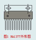
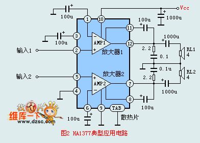

HA1377 is an audio power amplifier circuit produced by Hitachi, there are two teams of amplifier circuits on a silicon chip, the circuit has a big output power, when the voltage is 13.2v and the 4Ω loading is THD=10%, the output power is 5.8W. When TBL is connected, a power of 17W can be got under the above conditions. The circuit is used in portable, desk single channel and stereo dual-channel recorders, etc, the circuit can be in 12-pin single in-line plastic package, the outline is shown in Figure 1.The circuit features:1.the distortion is small.
(View)
View full Circuit Diagram | Comments | Reading(2864)
BA536--The 4.5W dual-channel power amplifier circuit
Published:2011/6/20 20:02:00 Author:Seven | Keyword: dual-channel, power amplifier
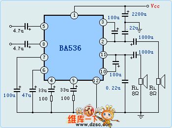
BA536 is a dual-channel power amplifier circuit, which characterizes good balance and little gain difference, the circuit is in 12-pin DIP in-line package, the features of the circuits are as follows. The output powers of each channel are 4.5w(when the loading impedance is 4Ω and the voltage of the power supply is 12v ) and 5.5W(when the loading impedance is 3Ω and the voltage of the power supply is 12v ). The wave rejection rate is 55dB, the distortion is THD=1.5% (when Po=0.5W), the crosstalk is lower than 57dB, the working voltage is 5-12v, which can compose a BTL easily. The limit parameter: Vcc=18V, power consumption: working temperature: -20-75℃.
(View)
View full Circuit Diagram | Comments | Reading(2714)
The toy car circuit controlled by the color TV remote control
Published:2011/6/23 2:19:00 Author:qqtang | Keyword: toy car, color TV, remote control
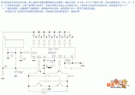
I reinstalled a toy car which can be used by the color TV remote control, the circuit is shown in the figure. P10~P17 connect with the lighting pipe as the 8-gear display; P3.5 and P3.7 control the advance of retreat of the motor, and the two can be in the low LEV at the same time, and they output a PWM square wave whose period is 80mS. The triode power is decided by the motor current. The keys of + and - control the heading direction, the sound volume key is used to control the speed, the power supply key is to control the pulling over of the toy car. The control distance is 18 meters, and it can be shaded by furnitures.
(View)
View full Circuit Diagram | Comments | Reading(794)
The simple circuit of long-distance control
Published:2011/6/22 6:55:00 Author:qqtang | Keyword: simple circuit, long-distance control
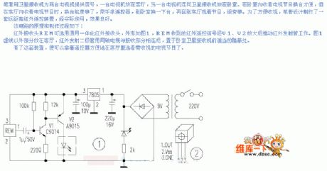
The principles and manufacturing process are as follows:The infrared receiver REM can be the general integral infrared receiver, the outline is shown in figure 1, the infrared remote signal received by REM is then magnified by V1 and V2 and pushes the infrared emitting pipe to work. In the figure, the part out of the hidden line is installed in the lounge room, after the infrared emitting diode is connected with the receiving part by the coaxial-cable, it is set in a hidden place in front of the satellite TV set in the living room. With this equipment, it is convenient for people to watch TV with the remote control in their hands.
(View)
View full Circuit Diagram | Comments | Reading(622)
Mazda 95TAURUS (without DRL) automatic and fog lights circuit
Published:2011/6/21 0:50:00 Author:John | Keyword: automatic and fog lights
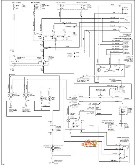
Mazda 95TAURUS (without DRL) automatic and fog lights circuit is shown.
(View)
View full Circuit Diagram | Comments | Reading(670)
Mazda 95TAURUS (3.8L) lamp monitor circuit
Published:2011/6/21 0:46:00 Author:John | Keyword: lamp monitor
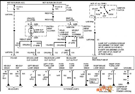
Mazda 95TAURUS (3.8L) lamp monitor circuit is shown.
(View)
View full Circuit Diagram | Comments | Reading(588)
Mazda 95TAURUS (3.8L) air-conditioning fan circuit
Published:2011/6/21 0:46:00 Author:John | Keyword: air-conditioning fan
Mazda 95TAURUS (3.8L) air-conditioning fan circuit is shown.
(View)
View full Circuit Diagram | Comments | Reading(701)
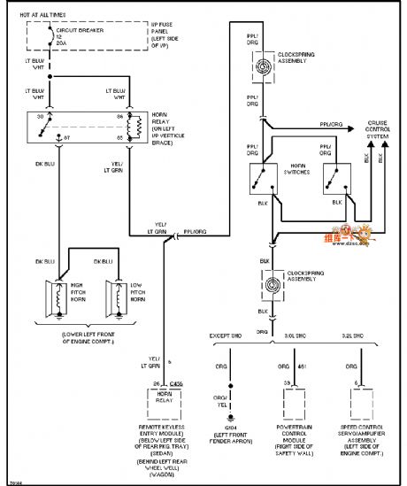
Mazda 95TAURUS shift interlock circuit
Published:2011/6/21 0:45:00 Author:John | Keyword: shift interlock
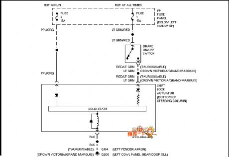
Mazda 95TAURUS shift interlock circuit is shown.
(View)
View full Circuit Diagram | Comments | Reading(684)
The Jinbei-Sea lion SY6480A2L-ME bus circuit
Published:2011/6/23 2:28:00 Author:qqtang | Keyword: Jinbei, Sea lion
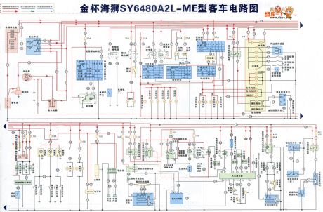
The Jinbei-Sea lion SY6480A2L-ME bus circuit is shown in the figure.
(View)
View full Circuit Diagram | Comments | Reading(541)
Mazda 95TAURUS power seat circuit
Published:2011/6/21 0:45:00 Author:John | Keyword: power seat
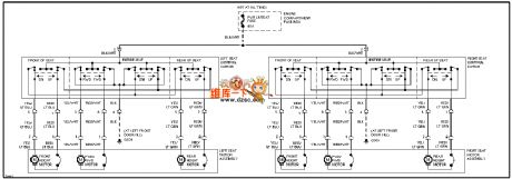
Mazda 95TAURUS power seat circuit is shown.
(View)
View full Circuit Diagram | Comments | Reading(659)
Mazda 95TAURUS power antenna circuit
Published:2011/6/21 0:45:00 Author:John | Keyword: power antenna
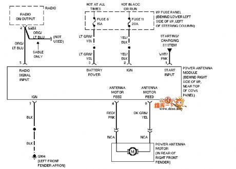
Mazda 95TAURUS power antenna circuit is shown.
(View)
View full Circuit Diagram | Comments | Reading(757)
Mazda 95TAURUS headlight circuit
Published:2011/6/21 0:45:00 Author:John | Keyword: headlight
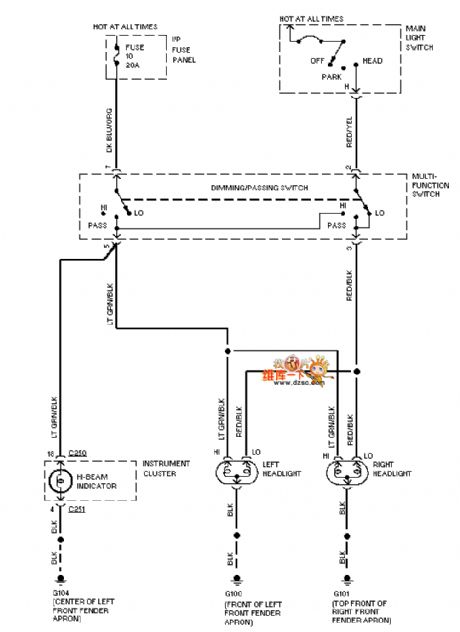
Mazda 95TAURUS headlight circuit is shown.
(View)
View full Circuit Diagram | Comments | Reading(809)
The high-voltage power supply and lower limit alarm circuit
Published:2011/6/22 1:39:00 Author:Borg | Keyword: high-voltage, power supply, lower limit

In the circuit is the high-voltage power supply and low limit alarm circuit. The circuit consists of the top limit alarm circuit and the lower limit alarm circuit. The right part is the lower limit alarm circuit: when the power supply voltage is close to the lower limit (but still normal), just adjust the potentiometer Wz, then the LEV of 556 8-pin is a little higher than 1/3VDD. When the power supply moves lower and makes the 8-pin LEV under l/3VDD, the 556 9-pin is reversing and outputting a high LEV, so the lower limit makes LED2 light. At the same time, the transistor BG is connected with 9-pin.
(View)
View full Circuit Diagram | Comments | Reading(813)
The BA328 stereo pre-amplifier circuit
Published:2011/6/20 21:00:00 Author:Seven | Keyword: stereo, pre-amplifier

BA328 has two lines of pre-amplifier circuits, it characterizes few external elements and convenient installation,etc. It is in a single 8-pin package. The features of the circuit are as follows: the working voltage is wide, the noise is weak, open loop gain is high and left-right channel balance is good. It is often used in cassette players, car stereo radios and domestic stereo equipment. The limit parameters of BA328 are as follows: the maximum voltage of the power supply is 18v, max power consumption is 540mW, working temperature is -25-70℃.
(View)
View full Circuit Diagram | Comments | Reading(5191)
Mazda 95TAURUS front wiper washer circuit
Published:2011/6/21 0:44:00 Author:John | Keyword: front wiper washer
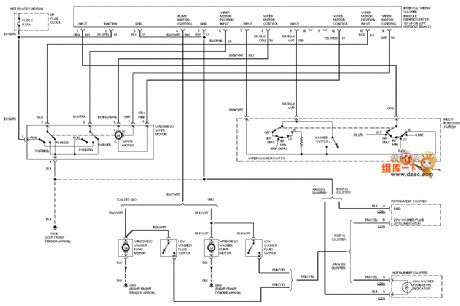
Mazda 95TAURUS front wiper washer circuit is just as shown.
(View)
View full Circuit Diagram | Comments | Reading(744)
The long-term timing circuit composed of 555
Published:2011/6/23 11:15:00 Author:qqtang | Keyword: long-term, timing circuit

In the figure is the long-term timing circuit composed of 555. When S1 is pressed, timing is starting, and the time can be changed by adjusting RP1, the timing range is 3~220min. If capacitor C1 is 2200μF, then the timing range is 40~48h. The 3-pin of 555 outputs the timing control signal. If the circuit is used to control large power controller, a relay can be fixed between B and C or A and B, the touch spot of the relay is to control all kinds of timing loading.
(View)
View full Circuit Diagram | Comments | Reading(1033)
| Pages:1730/2234 At 2017211722172317241725172617271728172917301731173217331734173517361737173817391740Under 20 |
Circuit Categories
power supply circuit
Amplifier Circuit
Basic Circuit
LED and Light Circuit
Sensor Circuit
Signal Processing
Electrical Equipment Circuit
Control Circuit
Remote Control Circuit
A/D-D/A Converter Circuit
Audio Circuit
Measuring and Test Circuit
Communication Circuit
Computer-Related Circuit
555 Circuit
Automotive Circuit
Repairing Circuit