Automotive Circuit
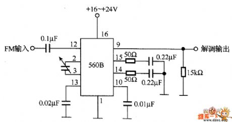
The FM demodulation circuit
Published:2011/6/20 9:39:00 Author:Seven | Keyword: FM demodulation | From:SeekIC

In the figure is the FM demodulation circuit instance, which converts the FM central frequency(10.7 MHz) into the low-frequency signal with 560B. The 560B chip contains the phase comparator, amplifier and voltage control oscillator. When the voltage control oscillator is synchronized with the input signal, the circuit engages in FM demodulation by using the character that the control voltage is proportional to the input signal frequency. When the maximum bias frequency is 75KHz from the central frequency of 10.7MHz, the low-frequency voltage peak value of the corresponding FM wave is 0.21v.
Reprinted Url Of This Article:
http://www.seekic.com/circuit_diagram/Automotive_Circuit/The_FM_demodulation_circuit.html
Print this Page | Comments | Reading(3)

Article Categories
power supply circuit
Amplifier Circuit
Basic Circuit
LED and Light Circuit
Sensor Circuit
Signal Processing
Electrical Equipment Circuit
Control Circuit
Remote Control Circuit
A/D-D/A Converter Circuit
Audio Circuit
Measuring and Test Circuit
Communication Circuit
Computer-Related Circuit
555 Circuit
Automotive Circuit
Repairing Circuit
Code: