Position: Home > Circuit Diagram > Measuring and Test Circuit > The PLL FM demodulator (LM565CN、RC4558DN) circuit
Measuring and Test Circuit
The PLL FM demodulator (LM565CN、RC4558DN) circuit
Published:2011/6/16 20:48:00 Author:qqtang | Keyword: FM demodulator | From:SeekIC

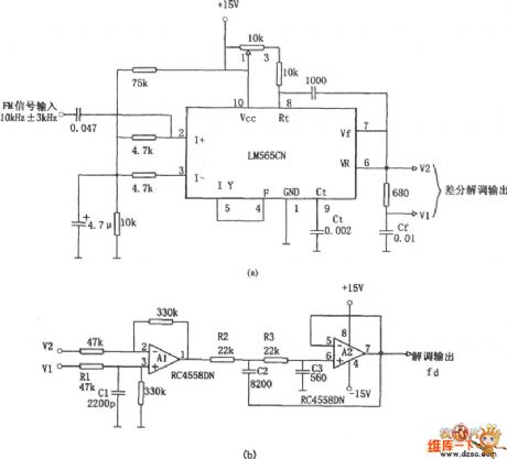
In the figure is a 10kHz±3kHz FM demodulator circuit consisting of LM565CN. The differential demodulation of V1 and V2 is level-shifted and amplified by A1 difference amplifier in figure (b), then the 20KHz pulse impulse momentum is removed by LPF composed of A2.
Reprinted Url Of This Article:
http://www.seekic.com/circuit_diagram/Measuring_and_Test_Circuit/The_PLL_FM_demodulator_LM565CN-RC4558DN_circuit.html
Print this Page | Comments | Reading(3)

Article Categories
power supply circuit
Amplifier Circuit
Basic Circuit
LED and Light Circuit
Sensor Circuit
Signal Processing
Electrical Equipment Circuit
Control Circuit
Remote Control Circuit
A/D-D/A Converter Circuit
Audio Circuit
Measuring and Test Circuit
Communication Circuit
Computer-Related Circuit
555 Circuit
Automotive Circuit
Repairing Circuit
Code: