555 Circuit
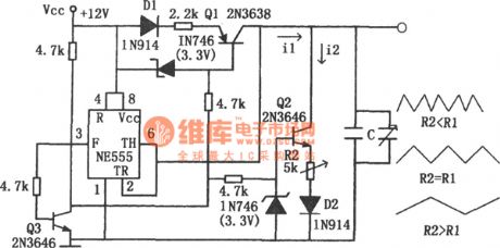
The adjustable symmetric triangular wave generator(NE555)
Published:2011/6/14 0:52:00 Author:Borg | Keyword: symmetric, triangular wave generator | From:SeekIC

In the circuit, the timer NE555 forms a triangular wave generator, whose working frequency can reach 100KHz or so. The transistors Q1 and Q2 in the figure form a switch constant current power supply whose state is controlled by Q3. When Q3 is conducting, the collector electrode is in the low LEV, at the moment, Q1 is conducting and charging the capacitor C with the constant current of i1, the voltage on the two terminals of C is a linear slope wave. When the two terminals of capacitor C are in a voltage of 2E/3 (the high trigger LEV of the timer), the 3-pin of the timer is in a low LEV, Q3 is blocked and the collecting electrode is in a high LEV.
Reprinted Url Of This Article:
http://www.seekic.com/circuit_diagram/555_Circuit/The_adjustable_symmetric_triangular_wave_generatorNE555.html
Print this Page | Comments | Reading(3)

Article Categories
power supply circuit
Amplifier Circuit
Basic Circuit
LED and Light Circuit
Sensor Circuit
Signal Processing
Electrical Equipment Circuit
Control Circuit
Remote Control Circuit
A/D-D/A Converter Circuit
Audio Circuit
Measuring and Test Circuit
Communication Circuit
Computer-Related Circuit
555 Circuit
Automotive Circuit
Repairing Circuit
Code: