Signal Processing
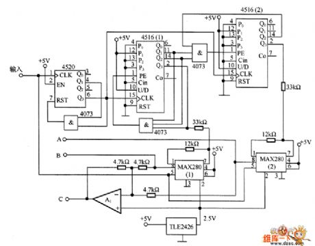
The 3-phase sine signal generator circuit
Published:2011/6/20 22:39:00 Author:Seven | Keyword: 3-phase, sine signal | From:SeekIC

In the figure is the 3-phase sine signal generator circuit. This kind of circuit is widely used, such as controlling the voltage of the synchronized motor rotor. In the circuit, 2 dual-counters 4516(1)and 4516(2) with the low-pass filters MAX280(1) and MAX280(2) generate the phase-A and phase-B signals of sine waveform, and the signals are added together by A1 and then there generates an inverting phase signal of C. To reduce the distortion of the waveform, the counter outputs symmetric signals, and the phase different would better be 120°.
Reprinted Url Of This Article:
http://www.seekic.com/circuit_diagram/Signal_Processing/The_3_phase_sine_signal_generator_circuit.html
Print this Page | Comments | Reading(3)

Article Categories
power supply circuit
Amplifier Circuit
Basic Circuit
LED and Light Circuit
Sensor Circuit
Signal Processing
Electrical Equipment Circuit
Control Circuit
Remote Control Circuit
A/D-D/A Converter Circuit
Audio Circuit
Measuring and Test Circuit
Communication Circuit
Computer-Related Circuit
555 Circuit
Automotive Circuit
Repairing Circuit
Code: