Signal Processing
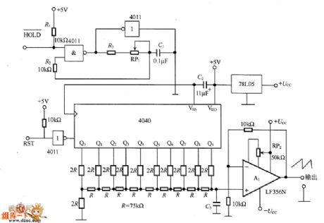
The low frequency sawtooth wave generating circuit
Published:2011/6/23 20:38:00 Author:Seven | Keyword: low frequency, sawtooth wave | From:SeekIC

In the figure is the low frequency sawtooth wave generating circuit. The circuit consists of the clock oscillator 4011, IO bit counter 4040, R2-R resistor ladder network, reference voltage generator 78LO5, buffer amplifier A1 and so on. The output wave is a ladder wave which splits the 0~10v into 1024 pieces equally(about 10mV). When the frequency is constant, the rising time can be prolonged by adding C3 and gets a smooth waveform.
Reprinted Url Of This Article:
http://www.seekic.com/circuit_diagram/Signal_Processing/The_low_frequency_sawtooth_wave_generating_circuit.html
Print this Page | Comments | Reading(3)

Article Categories
power supply circuit
Amplifier Circuit
Basic Circuit
LED and Light Circuit
Sensor Circuit
Signal Processing
Electrical Equipment Circuit
Control Circuit
Remote Control Circuit
A/D-D/A Converter Circuit
Audio Circuit
Measuring and Test Circuit
Communication Circuit
Computer-Related Circuit
555 Circuit
Automotive Circuit
Repairing Circuit
Code: