Audio Circuit
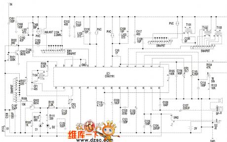
The multi-function radio principle circuit
Published:2011/6/17 0:26:00 Author:Seven | Keyword: multi-function radio | From:SeekIC

Notes: the audio signal which is output from 23-pin of u1 is coupled by C123 and input from 24-pin. W1 is the electric sound volume control potentiometer, which controls the sound volume of 4-pin of u1. The output audio signal of 23-pin of u1 is sent to the IC internal power amplifier of 24-pin of c1, after being amplified, the audio signal is output from 27-pin to drive the loudspeaker or headphone. The clock control and drive display circuit consists of the LED screen (ICD), SC361O, x1, c1, c6, R1-R5, swl-SW8, Q1 and other elements.
Reprinted Url Of This Article:
http://www.seekic.com/circuit_diagram/Audio_Circuit/The_multi_function_radio_principle_circuit.html
Print this Page | Comments | Reading(3)

Article Categories
power supply circuit
Amplifier Circuit
Basic Circuit
LED and Light Circuit
Sensor Circuit
Signal Processing
Electrical Equipment Circuit
Control Circuit
Remote Control Circuit
A/D-D/A Converter Circuit
Audio Circuit
Measuring and Test Circuit
Communication Circuit
Computer-Related Circuit
555 Circuit
Automotive Circuit
Repairing Circuit
Code: